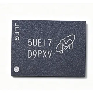
N25Q016A11ESCA0F - 16Mbit SPI NOR Flash 108MHz | Micron Technology
MPN: N25Q016A11ESCA0F ✓ Active| Qty | Unit Price | Extended |
|---|---|---|
| 1 | $1.25 | $1.25 |
| 10 | $1.12 | $11.20 |
| 100 | $0.95 | $95.00 |
| 500 | $0.84 | $420.00 |
| 1,000 | $0.74 | $740.00 |
Drop-in alternatives for N25Q016A11ESCA0F — same package, pin-to-pin compatible. Different-package parts requiring PCB rework are excluded.
Quick Comparison Tool — Select alternative parts for side-by-side comparison:
N25Q032A11ESCA0F
✅ Drop-In ⚠️ 参数待验证📋 Reference alternative (not in catalog)
N25Q016A11ESC A0G
✅ Drop-In ⚠️ 参数待验证📋 Reference alternative (not in catalog)
N25Q016A13ESCA0F
✅ Drop-In ⚠️ 参数待验证📋 Reference alternative (not in catalog)
W25Q16JVSSIQ
✅ Drop-In ⚠️ 参数待验证📋 Reference alternative (not in catalog)
GD25Q16CSIG
✅ Drop-In ⚠️ 参数待验证📋 Reference alternative (not in catalog)
MX25L1606E
✅ Drop-In ⚠️ 参数待验证📋 Reference alternative (not in catalog)
N25Q016A11ESCA0F Maximum Ratings & Electrical Characteristics
| Memory Type | SPI NOR Flash |
| Memory Size | 16 Mbit (2 Mbyte) |
| Organization | 2M x 8 |
| Interface | SPI |
| Maximum Clock Frequency | 108 MHz |
| Package | 8-SO (SOIC-8) |
| Mounting Type | Surface Mount |
N25Q016A11ESCA0F Pin Configuration
| Pin 1 | S# (CS#) — Chip select, active low |
| Pin 2 | DQ1 (DO/SO) — Serial data output / IO1 |
| Pin 3 | W# (WP#/IO2) — Write protect / IO2 |
| Pin 4 | VSS (GND) — Ground |
| Pin 5 | DQ0 (DI/SI) — Serial data input / IO0 |
| Pin 6 | SCK (C) — Serial clock input |
| Pin 7 | DQ3 (HOLD#) — Hold / IO3 |
| Pin 8 | VDD (VCC) — Power supply |
Safe Operating Area (SOA) & Thermal Characteristics
No official SOA curve available for this digital IC. Always operate within absolute maximum ratings specified in the datasheet. Ensure adequate cooling and derate as needed.
Typical Applications
N25Q016A11ESCA0F is suitable for 6 applications: BIOS / UEFI Boot Firmware Storage, FPGA Configuration Bitstream Storage, Microcontroller Firmware Storage, Networking Equipment Parameter Storage, Consumer Appliance Firmware, Industrial Control and Data Logging.
BIOS / UEFI Boot Firmware Storage
The N25Q016A11ESCA0F is a natural choice for BIOS and UEFI boot firmware storage on x86 embedded boards and single-board computers. Its 2 MB (16 Mbit) capacity accommodates compressed UEFI images for many embedded platforms, and the 108 MHz SPI clock keeps POST and boot times short by streaming firmware quickly at power-up. The standard SPI interface connects directly to the chipset's SPI controller without glue logic, and the 8-SO package occupies minimal board area near the southbridge or SoC. Because NOR flash offers random byte access, the CPU can execute-in-place (XIP) directly from the device during early boot, eliminating the need for a shadow-RAM copy step. Designers should place the flash close to the host controller, decouple VDD with 100 nF, and verify sector-erase endurance against firmware-update frequency for reliable long-term operation.
Recommended
FPGA Configuration Bitstream Storage
FPGAs commonly boot their configuration bitstream from SPI NOR flash, and the N25Q016A11ESCA0F fits this role for mid-range devices. A 2 MB device holds bitstreams for a wide range of FPGAs in the XC7A/Artix and ECP5 classes, and the 108 MHz clock minimizes configuration time so the FPGA becomes operational within tens of milliseconds. The master-SPI configuration mode of modern FPGAs drives the flash directly: CS# enables the device, the FPGA issues a fast-read command, and DQ0/DQ1 stream the bitstream. Pull W#/IO2 and HOLD#/DQ3 to inactive levels during power-up so the flash never enters write-protect or hold inadvertently. For multi-image designs (golden + upgrade bitstreams), the sector architecture permits safe in-field bitstream updates with rollback capability.
Recommended
Microcontroller Firmware Storage
In cost-sensitive embedded products, the N25Q016A11ESCA0F stores application firmware for microcontrollers whose internal flash is insufficient, enabling larger code images, asset storage (fonts, images, web files), and dual-bank update schemes. The standard SPI command set works with every MCU SPI peripheral, and page-program operation (256-byte pages typical for the N25Q family) allows efficient incremental writes. The 108 MHz clock supports fast image verification CRC passes after download. A common pattern is: MCU boots from internal flash, downloads new firmware over the network into external NOR, validates it, then reboots into the new image. The SOIC-8 footprint keeps BOM cost and board area low, and industrial temperature availability suits factory-floor equipment deployments.
Recommended
Networking Equipment Parameter Storage
Routers, switches, and access points use SPI NOR flash such as the N25Q016A11ESCA0F to store boot code, MAC addresses, calibration data, and configuration parameters that must survive power cycles. The device's NOR random-access behavior lets the network processor read individual configuration records without reading the whole array, and subsector erase granularity means one parameter block can be rewritten without erasing the boot image. The 108 MHz interface keeps access latency low during frequent configuration reads. For always-on networking hardware, endurance and retention matter: log-write patterns should be spread across sectors (wear-leveling in software) to maximize lifetime. The 8-SO package also simplifies second-sourcing, since the footprint accepts Winbond and GigaDevice equivalents with the same pinout.
Recommended
Consumer Appliance Firmware
Set-top boxes, smart TVs, white goods, and IoT appliances rely on SPI NOR flash for boot code and settings storage, and the N25Q016A11ESCA0F provides the standard 2 MB capacity used across these platforms. Its low pin count reduces connector and layout cost in high-volume consumer boards, and the SOIC-8 package is handled by every contract-manufacturing SMT line. Fast read at 108 MHz shortens cold-start times, which directly affects user-perceived boot performance in appliances. Consumer products often perform over-the-air updates: the sector architecture supports A/B firmware banks within 2 MB for compressed images, with the old image retained until the new one validates. Designers should add W#/IO2 write-protect hardware gating to guard settings regions against corrupted update attempts.
Recommended
Industrial Control and Data Logging
Industrial controllers, motor drives, and sensors use the N25Q016A11ESCA0F for parameter tables, calibration constants, fault logs, and boot code. NOR flash data integrity without refresh suits equipment that must retain settings through years of powered-down storage, and the device's erase-block architecture lets firmware rewrite a small logging sector without disturbing the code area. The industrial temperature option of the N25Q family supports control cabinets and outdoor enclosures where ambient temperatures swing widely. In noisy motor-drive environments, SPI signal integrity benefits from short, grounded traces and local 100 nF decoupling; software CRC checks on stored parameters add a final integrity layer. The standard footprint also eases long-term maintenance, since pin-compatible substitutes exist across Micron, Winbond, and GigaDevice catalogs.
Recommended
Recommended Products Summary
Engineering reference data for N25Q016A11ESCA0F — comparison, design guidance, and compliance information.
Selection Guide
Comparison with Alternatives
| Parameter | This Product | N25Q032A11ESCA0F | W25Q16JVSSIQ | GD25Q16CSIG | MX25L1606E |
|---|---|---|---|---|---|
| Package | 8-SO (SOIC-8) | 8-SO (SOIC-8) - same | SOIC-8 (208 mil) - same footprint | SOP-8 - same footprint | SOP-8 - same footprint |
| Brand | Micron Technology | Micron Technology | Winbond | GigaDevice | Macronix |
| Memory Size | 16 Mbit (2 MB) | 32 Mbit (4 MB) | 16 Mbit (2 MB) | 16 Mbit (2 MB) | 16 Mbit (2 MB) |
| Max SPI Clock | 108 MHz | 108 MHz | 133 MHz | [DATA_NEEDED] | 86 MHz |
| Interface | SPI (standard/dual/quad capable family) | SPI (standard/dual/quad) | SPI (standard/dual/quad) | SPI (standard/dual/quad) | SPI (standard/dual/quad) |
| Command Set Compatibility | Micron N25Q native | Identical (same family) | Core commands compatible; vendor extensions differ | Core commands compatible; status bits differ | Core commands compatible; vendor extensions differ |
| Density Headroom for Firmware Updates | 2 MB (single image + settings typical) | 4 MB - supports A/B banks comfortably | 2 MB - same headroom | 2 MB - same headroom | 2 MB - same headroom |
| Indicative Unit Price (qty 1, as of 2026-09-04) | $1.25 | [DATA_NEEDED] | [DATA_NEEDED] | [DATA_NEEDED] | [DATA_NEEDED] |
Key Differentiators
- Higher SPI clock headroom than legacy alternatives (vs MX25L1606E)
- Family density upgrade path with zero footprint change (vs N25Q032A11ESCA0F)
- Micron N25Q command architecture for XIP boot (vs GD25Q16CSIG)
Design Notes
Place a 100 nF ceramic decoupling capacitor within 3-5 mm of the VDD pin (pin 8) and keep the VSS return (pin 4) to a solid ground plane. At 108 MHz SPI operation, treat SCK, DQ0, and DQ1 as transmission-line-aware nets: keep them under ~50 mm where possible, avoid crossing plane splits, and route away from switching regulator nodes. For multi-drop or long SPI buses, add 22-33 ohm series resistors at the driver to dampen ringing and reduce EMI emissions.
During power-up, W#/IO2 (pin 3) and HOLD#/DQ3 (pin 7) must be at defined levels before the first read command, or the device may enter write-protect or hold state and appear unresponsive. Use 10 kohm pull-ups to VDD on both pins when they are not actively driven. This is especially important in FPGA master-SPI configuration designs, where an undefined IO2/IO3 state will silently stall bitstream loading and appear as a blank FPGA.
When substituting cross-brand SOIC-8 flash (Winbond, GigaDevice, Macronix), core read/program/erase commands are compatible, but status-register bit definitions, security registers, and advanced commands are not. Driver code that polls status bits or uses vendor-specific commands (e.g., Micron flag-status, RESET, extended address) must be validated against the replacement datasheet. Also verify the supply voltage class encoded in the part suffix matches your rail before dropping in any alternative - this is the most common substitution failure.
Compliance Information
Compliance data not present in the provided Verified Web Data. The -F suffix in Micron N25Q part numbering conventionally indicates lead-free/RoHS flow, but this must be confirmed on Micron's official product page before use in compliance documentation.