STM32H7B3ZIT6 - 280MHz Cortex-M7 MCU, 2MB Flash | STMicroelectronics
MPN: STM32H7B3ZIT6 ✓ Active| Qty | Unit Price | Extended |
|---|---|---|
| 1 | $12.5 | $12.50 |
| 10 | $11.25 | $112.50 |
| 100 | $10 | $1,000.00 |
| 500 | $9 | $4,500.00 |
| 1,000 | $8.1 | $8,100.00 |
Drop-in alternatives for STM32H7B3ZIT6 — same package, pin-to-pin compatible. Different-package parts requiring PCB rework are excluded.
Quick Comparison Tool — Select alternative parts for side-by-side comparison:
STM32H7A3ZIT6
✅ Drop-In📋 Reference alternative (not in catalog)
STM32H7B0ZIT6
✅ Drop-In📋 Reference alternative (not in catalog)
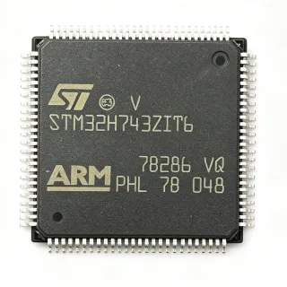
STM32H743ZIT6
✅ Drop-In✓ In Stock
$9.2273 / Unit
View Datasheet →STM32H753ZIT6
✅ Drop-In✓ In Stock
$11.75 / Unit
View Datasheet →STM32H750ZBT6
✅ Drop-In📋 Reference alternative (not in catalog)
STM32H7B3ZIT6 Maximum Ratings & Electrical Characteristics
| Core | Arm Cortex-M7 |
| Max Clock Speed | 280 MHz |
| Flash Memory | 2 MB |
| SRAM | 1.4 MB |
| Package | LQFP144 (20x20 mm) |
| Supply Voltage | 1.62 V to 3.6 V |
| Operating Temperature | -40C to +85C |
| GPIO Pins | 114 |
| ADC | 3x 16-bit, 3.6 MSPS |
| DAC | 2x 12-bit |
| Communication Interfaces | Ethernet, USB OTG HS, 4x USART, 4x SPI, 4x I2C, 2x FDCAN |
| Timers | 20x 16-bit, 2x 32-bit |
| DMA | 2x DMA controllers with 16 streams each |
| Cryptographic Acceleration | AES, DES, 3DES, SHA-1, SHA-256 |
| CoreMark | 856 |
| RoHS Status | Compliant |
STM32H7B3ZIT6 Pin Configuration
| Pin 1 | PE2 — GPIO / alternate functions |
| Pin 2 | PE3 — GPIO / alternate functions |
| Pin 3 | PE4 — GPIO / alternate functions |
| Pin 4 | PE5 — GPIO / alternate functions |
| Pin 5 | PE6 — GPIO / alternate functions |
| Pin 6 | VBAT — Backup battery supply |
| Pin 7 | PC13 — GPIO / RTC tamper |
| Pin 8 | PC14 — GPIO / OSC32_IN |
| Pin 9 | PC15 — GPIO / OSC32_OUT |
| Pin 10 | PF0 — GPIO / alternate functions |
| Pin 11 | PF1 — GPIO / alternate functions |
| Pin 12 | PF2 — GPIO / alternate functions |
| Pin 13 | PF3 — GPIO / alternate functions |
| Pin 14 | PF4 — GPIO / alternate functions |
| Pin 15 | PF5 — GPIO / alternate functions |
| Pin 16 | PF6 — GPIO / alternate functions |
| Pin 17 | PF7 — GPIO / alternate functions |
| Pin 18 | PF8 — GPIO / alternate functions |
| Pin 19 | PF9 — GPIO / alternate functions |
| Pin 20 | PF10 — GPIO / alternate functions |
| Pin 21 | VSS — Ground |
| Pin 22 | VDD — Digital power supply |
| Pin 23 | PF11 — GPIO / alternate functions |
| Pin 24 | PF12 — GPIO / alternate functions |
| Pin 25 | PF13 — GPIO / alternate functions |
| Pin 26 | PF14 — GPIO / alternate functions |
| Pin 27 | PF15 — GPIO / alternate functions |
| Pin 28 | PG0 — GPIO / alternate functions |
| Pin 29 | PG1 — GPIO / alternate functions |
| Pin 30 | PG2 — GPIO / alternate functions |
| Pin 31 | PG3 — GPIO / alternate functions |
| Pin 32 | PG4 — GPIO / alternate functions |
| Pin 33 | PG5 — GPIO / alternate functions |
| Pin 34 | PG6 — GPIO / alternate functions |
| Pin 35 | PG7 — GPIO / alternate functions |
| Pin 36 | PG8 — GPIO / alternate functions |
| Pin 37 | PG9 — GPIO / alternate functions |
| Pin 38 | PG10 — GPIO / alternate functions |
| Pin 39 | PG11 — GPIO / alternate functions |
| Pin 40 | PG12 — GPIO / alternate functions |
| Pin 41 | PG13 — GPIO / alternate functions |
| Pin 42 | PG14 — GPIO / alternate functions |
| Pin 43 | PG15 — GPIO / alternate functions |
| Pin 44 | VSS — Ground |
| Pin 45 | VDD — Digital power supply |
| Pin 46 | PH0 — GPIO / OSC_IN |
| Pin 47 | PH1 — GPIO / OSC_OUT |
| Pin 48 | NRST — Reset (active low) |
| Pin 49 | PC0 — GPIO / ADC input |
| Pin 50 | PC1 — GPIO / ADC input |
| Pin 51 | PC2 — GPIO / ADC input |
| Pin 52 | PC3 — GPIO / ADC input |
| Pin 53 | VSSA — Analog ground |
| Pin 54 | VDDA — Analog power supply |
| Pin 55 | PC4 — GPIO / ADC input |
| Pin 56 | PC5 — GPIO / ADC input |
| Pin 57 | PB0 — GPIO / ADC input |
| Pin 58 | PB1 — GPIO / ADC input |
| Pin 59 | PB2 — GPIO / alternate functions |
| Pin 60 | PB3 — GPIO / alternate functions |
| Pin 61 | PB4 — GPIO / alternate functions |
| Pin 62 | PB5 — GPIO / alternate functions |
| Pin 63 | PB6 — GPIO / alternate functions |
| Pin 64 | PB7 — GPIO / alternate functions |
| Pin 65 | BOOT0 — Boot mode selection |
| Pin 66 | PB8 — GPIO / alternate functions |
| Pin 67 | PB9 — GPIO / alternate functions |
| Pin 68 | PE7 — GPIO / alternate functions |
| Pin 69 | PE8 — GPIO / alternate functions |
| Pin 70 | PE9 — GPIO / alternate functions |
| Pin 71 | PE10 — GPIO / alternate functions |
| Pin 72 | PE11 — GPIO / alternate functions |
| Pin 73 | PE12 — GPIO / alternate functions |
| Pin 74 | PE13 — GPIO / alternate functions |
| Pin 75 | PE14 — GPIO / alternate functions |
| Pin 76 | PE15 — GPIO / alternate functions |
| Pin 77 | PB10 — GPIO / alternate functions |
| Pin 78 | PB11 — GPIO / alternate functions |
| Pin 79 | VSS — Ground |
| Pin 80 | VDD — Digital power supply |
| Pin 81 | PB12 — GPIO / alternate functions |
| Pin 82 | PB13 — GPIO / alternate functions |
| Pin 83 | PB14 — GPIO / alternate functions |
| Pin 84 | PB15 — GPIO / alternate functions |
| Pin 85 | PD8 — GPIO / alternate functions |
| Pin 86 | PD9 — GPIO / alternate functions |
| Pin 87 | PD10 — GPIO / alternate functions |
| Pin 88 | PD11 — GPIO / alternate functions |
| Pin 89 | PD12 — GPIO / alternate functions |
| Pin 90 | PD13 — GPIO / alternate functions |
| Pin 91 | PD14 — GPIO / alternate functions |
| Pin 92 | PD15 — GPIO / alternate functions |
| Pin 93 | PA0 — GPIO / ADC input / WKUP |
| Pin 94 | PA1 — GPIO / ADC input |
| Pin 95 | PA2 — GPIO / USART2_TX |
| Pin 96 | PA3 — GPIO / USART2_RX |
| Pin 97 | VSS — Ground |
| Pin 98 | VDD — Digital power supply |
| Pin 99 | PA4 — GPIO / DAC_OUT1 |
| Pin 100 | PA5 — GPIO / DAC_OUT2 |
| Pin 101 | PA6 — GPIO / ADC input |
| Pin 102 | PA7 — GPIO / ADC input |
| Pin 103 | PC4 — GPIO / ADC input |
| Pin 104 | PC5 — GPIO / ADC input |
| Pin 105 | PB0 — GPIO / ADC input |
| Pin 106 | PB1 — GPIO / ADC input |
| Pin 107 | PB2 — GPIO / alternate functions |
| Pin 108 | PB3 — GPIO / alternate functions |
| Pin 109 | PB4 — GPIO / alternate functions |
| Pin 110 | PB5 — GPIO / alternate functions |
| Pin 111 | PB6 — GPIO / alternate functions |
| Pin 112 | PB7 — GPIO / alternate functions |
| Pin 113 | BOOT0 — Boot mode selection |
| Pin 114 | PB8 — GPIO / alternate functions |
| Pin 115 | PB9 — GPIO / alternate functions |
| Pin 116 | PE7 — GPIO / alternate functions |
| Pin 117 | PE8 — GPIO / alternate functions |
| Pin 118 | PE9 — GPIO / alternate functions |
| Pin 119 | PE10 — GPIO / alternate functions |
| Pin 120 | PE11 — GPIO / alternate functions |
| Pin 121 | PE12 — GPIO / alternate functions |
| Pin 122 | PE13 — GPIO / alternate functions |
| Pin 123 | PE14 — GPIO / alternate functions |
| Pin 124 | PE15 — GPIO / alternate functions |
| Pin 125 | PB10 — GPIO / alternate functions |
| Pin 126 | PB11 — GPIO / alternate functions |
| Pin 127 | VSS — Ground |
| Pin 128 | VDD — Digital power supply |
| Pin 129 | PB12 — GPIO / alternate functions |
| Pin 130 | PB13 — GPIO / alternate functions |
| Pin 131 | PB14 — GPIO / alternate functions |
| Pin 132 | PB15 — GPIO / alternate functions |
| Pin 133 | PD8 — GPIO / alternate functions |
| Pin 134 | PD9 — GPIO / alternate functions |
| Pin 135 | PD10 — GPIO / alternate functions |
| Pin 136 | PD11 — GPIO / alternate functions |
| Pin 137 | PD12 — GPIO / alternate functions |
| Pin 138 | PD13 — GPIO / alternate functions |
| Pin 139 | PD14 — GPIO / alternate functions |
| Pin 140 | PD15 — GPIO / alternate functions |
| Pin 141 | PA0 — GPIO / ADC input / WKUP |
| Pin 142 | PA1 — GPIO / ADC input |
| Pin 143 | PA2 — GPIO / USART2_TX |
| Pin 144 | PA3 — GPIO / USART2_RX |
Safe Operating Area (SOA) & Thermal Characteristics
No official SOA curve available for this digital IC. Always operate within absolute maximum ratings specified in the datasheet. Ensure adequate cooling and derate as needed.
Typical Applications
STM32H7B3ZIT6 is suitable for 6 applications: Industrial Automation, Human-Machine Interface (HMI), Motor Control, Audio Processing, IoT Gateway, Medical Devices.
Industrial Automation
The STM32H7B3ZIT6 is ideal for industrial automation controllers due to its high clock speed, rich communication interfaces (Ethernet, FDCAN, USART), and advanced timers for precise motor control. It can handle complex PLC logic, real-time control loops, and HMI interfaces simultaneously. The 2 MB flash allows storing large firmware and data logs, while the 1.4 MB SRAM supports large data buffers for industrial protocols. The device's robust operating temperature range (-40°C to +85°C) ensures reliability in factory environments. Its cryptographic acceleration enhances secure communication in industrial IoT applications.
Recommended
Human-Machine Interface (HMI)
The STM32H7B3ZIT6 excels in HMI applications with its Chrom-ART Accelerator, which offloads 2D graphics rendering from the CPU, enabling smooth animations and responsive touch interfaces. The device supports external SDRAM via its flexible memory controller, allowing large frame buffers for high-resolution displays. The 280 MHz Cortex-M7 core handles complex UI logic and communication with ease. The device's rich peripheral set includes LTDC (LCD-TFT controller) and DSI host, simplifying display integration. The 2 MB flash provides ample storage for GUI assets and fonts. This makes it suitable for smart home panels, industrial HMIs, and medical devices.
Recommended
Motor Control
The STM32H7B3ZIT6 is well-suited for motor control applications, including field-oriented control (FOC) of BLDC and PMSM motors. Its advanced timers generate complementary PWM signals with dead-time insertion, while the 16-bit ADC with 3.6 MSPS provides high-speed current sensing. The device's high clock speed ensures fast control loop execution, and the 2 MB flash allows storing complex control algorithms and safety routines. The FDCAN interface enables communication with industrial drives. The device's cryptographic acceleration can be used for secure firmware updates. The wide supply voltage range and industrial temperature range make it robust for motor drive environments.
Recommended
Audio Processing
The STM32H7B3ZIT6 is capable of high-quality audio processing due to its high clock speed and DSP instructions. It can handle audio codecs, effects processing, and audio streaming. The device includes I2S interfaces for connecting audio codecs, and its DMA controllers enable efficient data transfer. The 1.4 MB SRAM allows buffering large audio samples, and the 2 MB flash can store audio data or firmware. The Chrom-ART Accelerator can be used for audio visualizations. The device's low-latency interrupt handling ensures real-time audio performance. This makes it suitable for audio interfaces, smart speakers, and professional audio equipment.
Recommended
IoT Gateway
The STM32H7B3ZIT6 is an excellent choice for IoT gateways due to its Ethernet MAC, USB OTG, and multiple communication interfaces. It can aggregate data from various sensors and devices, process it locally, and transmit to the cloud via Ethernet or Wi-Fi (using external modules). The device's cryptographic acceleration ensures secure data transmission and firmware updates. The 2 MB flash and 1.4 MB SRAM provide ample resources for protocol stacks and data buffering. The device's low-power modes enable energy-efficient operation. This makes it suitable for smart building controllers, industrial IoT gateways, and edge computing nodes.
Recommended
Medical Devices
The STM32H7B3ZIT6 is suitable for medical devices such as patient monitors, infusion pumps, and diagnostic equipment. Its high performance enables real-time signal processing, while the rich peripheral set supports various sensors and displays. The device's cryptographic acceleration can secure patient data. The 2 MB flash allows storing complex algorithms and patient data logs. The device's reliability and long-term availability make it suitable for medical applications. The industrial temperature range ensures operation in clinical environments. The device's low-power modes are beneficial for battery-powered portable medical devices.
Recommended
Recommended Products Summary
Engineering reference data for STM32H7B3ZIT6 — comparison, design guidance, and compliance information.
Selection Guide
Comparison with Alternatives
| Parameter | This Product | STM32H7A3ZIT6 | STM32H7B0ZIT6 | STM32H743ZIT6 | STM32H753ZIT6 | STM32H750ZBT6 |
|---|---|---|---|---|---|---|
| Package | LQFP144 | LQFP144 | LQFP144 | LQFP144 | LQFP144 | LQFP144 |
| Brand | STMicroelectronics | STMicroelectronics | STMicroelectronics | STMicroelectronics | STMicroelectronics | STMicroelectronics |
| Max Clock Speed | 280 MHz | 280 MHz | 280 MHz | 480 MHz | 480 MHz | 480 MHz |
| Flash Memory | 2 MB | 2 MB | 2 MB | 2 MB | 2 MB | 128 KB |
| SRAM | 1.4 MB | 1.4 MB | 1.4 MB | 1 MB | 1 MB | 1 MB |
| Chrom-ART Accelerator | Yes | No | No | No | No | No |
| Ethernet MAC | Yes | Yes | Yes | Yes | Yes | Yes |
| Cryptographic Acceleration | Yes | Yes | Yes | Yes | Yes | Yes |
Key Differentiators
- Chrom-ART Accelerator for 2D graphics (vs STM32H743ZIT6)
- Higher SRAM capacity (1.4 MB) (vs STM32H743ZIT6)
- Lower power consumption at 280 MHz (vs STM32H743ZIT6)
Design Notes
The STM32H7B3ZIT6 requires a stable power supply. Use a 100nF decoupling capacitor on each VDD pin and a 4.7uF bulk capacitor on the main supply. The VDDA pin should be filtered with a ferrite bead and a 1uF capacitor to reduce analog noise. Ensure the supply voltage is within 1.62V to 3.6V. For low-power operation, the internal LDO can be bypassed by connecting VCAP pins to an external capacitor, but follow the datasheet recommendations.
For the LQFP144 package, ensure proper grounding and thermal relief. Use a solid ground plane and place vias near the ground pins. The exposed pad (if present) should be soldered to the ground plane for thermal dissipation. Keep high-speed traces short and avoid routing near the crystal oscillator pins. Follow the layout guidelines in the STM32H7 hardware development application note (AN4666).
A common pitfall is incorrect boot configuration. The BOOT0 pin must be set correctly to boot from flash, system memory, or SRAM. Also, ensure the HSE crystal is properly connected with load capacitors as specified in the datasheet. Do not exceed the absolute maximum ratings on any pin. For firmware development, use the STM32CubeH7 software package and STM32CubeProgrammer for flashing.
Compliance Information
RoHS and REACH compliant per STMicroelectronics product page. Not AEC-Q100 qualified; for automotive, consider STM32H7A3ZIT6Q or other automotive-grade variants.