ADG1436YCPZ-500RL7 - 2Ohm Dual SPDT iCMOS Switch | Analog Devices
MPN: ADG1436YCPZ-500RL7 ✓ Active| Qty | Unit Price | Extended |
|---|---|---|
| 1 | $4.2 | $4.20 |
| 10 | $3.78 | $37.80 |
| 100 | $3.15 | $315.00 |
| 500 | $2.73 | $1,365.00 |
| 1,000 | $2.31 | $2,310.00 |
ADG1436YCPZ-500RL7 Overview
An analog switch is an electronic component that routes or gates analog signals by opening and closing MOSFET conduction paths under digital logic control. Within the signal-chain hierarchy, switches sit alongside multiplexers and demultiplexers as building blocks of analog signal routing, feeding signal conditioners, ADCs, and instrumentation front ends. Switches such as the ADG1436 form the interface layer between mixed-signal controllers and the analog world.
Key features of the ADG1436 include a maximum on-resistance of 2 ohm, 0.1 ohm on-resistance match between channels, 0.5 ohm max on-resistance flatness, and continuous current per channel of up to 400 mA in the LFCSP package (260 mA in the TSSOP variant). The device operates over a 33 V supply range and requires no VL logic supply - 3 V logic-compatible inputs work directly, simplifying interfacing with low-voltage controllers in high-voltage systems.
The iCMOS process technology combines high-voltage CMOS with submicron geometry, enabling rail-to-rail switching operation with high-voltage supplies while keeping quiescent power very low. Each of the two independently selectable SPDT switches is controlled by its own IN logic pin, and on the LFCSP package an EN input disables all channels when asserted, reducing power consumption in idle states.
Typical applications cited in the manufacturer datasheet include automatic test equipment, data acquisition systems, sample-and-hold circuits, audio signal routing, communication systems, relay replacement, and battery-powered systems.
When designing with this part, account for on-resistance in series with the signal path: at 400 mA continuous current, a 2 ohm switch dissipates roughly 0.32 W, so PCB copper around the LFCSP leads matters. Keep the EN pin logic levels within the 3 V-compatible input threshold range for reliable channel selection.
This page synthesizes drop-in alternatives, distributor sourcing context, and practical design notes not found in the manufacturer datasheet, providing engineers a single citable reference for the ADG1436YCPZ-500RL7.
Drop-in alternatives for ADG1436YCPZ-500RL7 — same package, pin-to-pin compatible. Different-package parts requiring PCB rework are excluded.
Variants in this series
Same-series models that are drop-in compatible with ADG1436YCPZ-500RL7 (same form factor and footprint) — differing in Package, RoHS Status, Switch Configuration.
Quick Comparison Tool — Select alternative parts for side-by-side comparison:
ADG1236YCPZ-500RL7
✅ Drop-In✓ In Stock
$5.27 / Unit
View Datasheet →ADG1436YCPZ-REEL
✅ Drop-In📋 Reference alternative (not in catalog)
ADG1436YCPZ-500RL7 Maximum Ratings & Electrical Characteristics
| Switch Configuration | Dual SPDT (2 x 2:1) |
| On Resistance (Max) | 2 ohm |
| On Resistance Match Between Channels | 0.1 ohm |
| On Resistance Flatness | 0.5 ohm (max) |
| Supply Voltage | +/-15 V / +12 V / +/-5 V (33 V supply range) |
| Continuous Current per Channel (LFCSP) | up to 400 mA |
| Logic Input Compatibility | 3 V logic-compatible, no VL supply required |
| Enable Input | Yes (EN, disables all channels on LFCSP package) |
| Operation | Rail-to-rail switching |
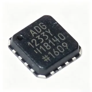
| Package | 16-lead LFCSP (QCC16, HVQCCN), 4 mm x 4 mm, MO-220VGGC |
| Mounting Type | Surface Mount |
| Temperature Grade | Automotive |
| Number of Terminals | 16 |
| Package Shape | Square |
| Technology | iCMOS (high-voltage CMOS) |
| Applications | ATE, data acquisition, audio routing, relay replacement |
| RoHS Status | unknown |
ADG1436YCPZ-500RL7 square Pin Configuration Guide
Pin configuration for ADG1436YCPZ-500RL7 (square package). Pin numbering, functions, and connection diagrams are defined in the manufacturer datasheet. Refer to it for the exact footprint and soldering guidelines.

No detailed pinout data available for ADG1436YCPZ-500RL7.
Refer to the datasheet for full pin configuration.
Typical Applications
ADG1436YCPZ-500RL7 is suitable for 6 applications: Automatic Test Equipment, Data Acquisition Systems, Relay Replacement, Sample-and-Hold Systems, Audio Signal Routing, Battery-Powered Systems.
Automatic Test Equipment
Automatic test equipment (ATE) routes stimulus and measurement signals to dozens of device-under-test pins, and switch error directly degrades test accuracy. The ADG1436YCPZ-500RL7 fits this role because its 2 ohm maximum on-resistance and 0.1 ohm channel match keep series loss and channel-to-channel gain mismatch negligible, while 400 mA continuous current per channel in the LFCSP package covers most functional-test source loads. The iCMOS process supports +/-15 V signal swings, allowing the switch to sit directly in instrument-grade analog front ends without extra level translation, and the EN pin lets the tester power down unused routing banks to save power. Specify this part wherever relay arrays are too slow or wear out too fast.
Recommended
Data Acquisition Systems
In data acquisition systems, dual SPDT switches select between signal sources, shunt calibration references, and ADC front ends. The ADG1436YCPZ-500RL7 is well suited because 0.5 ohm on-resistance flatness minimizes signal-dependent gain error across the input voltage range, and rail-to-rail operation at +/-15 V, +12 V, or +/-5 V covers industrial ADC input spans. Because the logic inputs are 3 V compatible with no VL supply required, a low-voltage microcontroller can sequence channels directly while the switch handles high-voltage analog signals - a common requirement in industrial DAQ. The 4x4 mm LFCSP-16 also saves board area relative to relay modules, and the -500 automotive grade supports harsh-environment acquisition nodes.
Recommended
Relay Replacement
Electromechanical relays in signal paths suffer from contact bounce, limited mechanical life, slow switching, and coil power draw. The ADG1436YCPZ-500RL7 replaces relays where load current stays within its 400 mA continuous per-channel rating (LFCSP package): its 2 ohm maximum on-resistance approaches contact-level resistance, and the iCMOS +/-15 V capability handles typical instrumentation signal swings. Switching is fast and bounce-free, improving throughput in automated routing matrices, and the EN input allows entire switch banks to be disabled, dropping system idle power - impossible with always-coiled relays. Note the trade-off: solid-state switching adds series resistance and imposes semiconductor current limits, so verify load current and fault conditions before dropping in this part.
Recommended
Sample-and-Hold Systems
Sample-and-hold circuits demand a switch with low charge injection, low leakage, and low on-resistance so the hold capacitor charges quickly and accurately then retains voltage during hold. The ADG1436YCPZ-500RL7 supports this with 2 ohm on-resistance for fast acquisition settling into the hold capacitor and rail-to-rail switching at +/-15 V or +/-5 V supplies typical of precision analog chains. Because it is fully specified at +/-5 V, it pairs naturally with low-voltage S/H amplifiers, while 3 V-compatible logic lets a fast ADC controller drive acquisition timing without a level shifter. The dual SPDT configuration allows a differential sample-and-hold pair from a single package, keeping channel matching tight via the 0.1 ohm RON match.
Recommended
Audio Signal Routing
Audio routing matrices use analog switches to select sources and route line-level signals to amplifiers or converters. The ADG1436YCPZ-500RL7 suits professional audio because its 2 ohm on-resistance drives headphone or line drivers with minimal insertion loss, and the 0.1 ohm channel match preserves stereo balance in L/R pairs handled by the two independent SPDT switches in one package. Rail-to-rail operation at +/-15 V comfortably accommodates pro-audio signal headroom, so large signal swings are not clipped by supply limits. The 400 mA current capability even allows light loads such as small speakers or headphone feeds through the switch. Breaking-before-make switching behavior in SPDT selection reduces source-to-source audible clicks in multiplexed audio paths.
Recommended
Battery-Powered Systems
Battery-powered instrumentation benefits from switches that route signals with minimal power overhead. The ADG1436YCPZ-500RL7 offers low CMOS quiescent power and an EN input on the LFCSP package that disables all channels, effectively zeroing switch consumption between measurement bursts. Because no VL supply is required, a single battery rail (or +/-5 V pair) powers the device while 3 V logic from the microcontroller directly controls channel selection, removing level-shifter current draw. The 2 ohm on-resistance keeps series loss low, which extends battery life in current-measurement paths. Designers should still switch EN off during sleep rather than leaving channels selected, since unselected CMOS switches leak proportionally to applied signal voltage.
Recommended
Recommended Products Summary
Engineering reference data for ADG1436YCPZ-500RL7 — comparison, design guidance, and compliance information.
Selection Guide
Comparison with Alternatives
| Parameter | This Product | ADG1236YCPZ-500RL7 | ADG1436YCPZ-REEL |
|---|---|---|---|
| Package | 16-lead LFCSP (4x4 mm) | 16-lead LFCSP (4x4 mm) - same | 16-lead LFCSP (4x4 mm) - same |
| Brand | Analog Devices | Analog Devices | Analog Devices |
| Switch Configuration | Dual SPDT | Dual SPDT | Dual SPDT |
| On Resistance (Max) | 2 ohm | higher RON (low-power variant) | 2 ohm |
| Supply Voltage | +/-15 V / +12 V / +/-5 V | +/-15 V / +12 V / +/-5 V | +/-15 V / +12 V / +/-5 V |
| Temperature Grade | Automotive (-500) | Automotive (-500) | Standard grade |
| Enable (EN) Pin | Yes (LFCSP) | Yes (LFCSP) | Yes (LFCSP) |
Key Differentiators
- Lowest on-resistance in the +/-15 V dual SPDT class (vs ADG1236YCPZ-500RL7)
- Automotive -500 temperature grade on tape-and-reel (vs ADG1436YCPZ-REEL)
- No VL logic supply required (vs ADG1236YCPZ-500RL7)
Design Notes
Estimated: at the 400 mA continuous current limit with 2 ohm maximum on-resistance, the switch dissipates P = I^2 x R = 0.4^2 x 2 = 0.32 W. For routing matrices driving many channels simultaneously, sum dissipation across both SPDT switches and verify the LFCSP-16 4x4 mm thermal path can handle the total; a solid ground plane with multiple thermal vias under the exposed pad is the standard approach. If sustained currents exceed a few hundred mA, consider distributing the load across two packages or using the TSSOP variant only below its 260 mA rating.
The LFCSP-16 uses a center exposed pad that must be soldered to a ground pour for both electrical return and heat spreading. Place the digital control traces (IN1, IN2, EN) away from high-current analog paths through the switches to prevent ground-bounce coupling into the signal. Keep analog switching nodes short and symmetric between the two SPDT halves to exploit the 0.1 ohm on-resistance match for differential circuits. Follow the land pattern in the ADG1436 datasheet MO-220VGGC outline exactly, since the 0.5 mm lead pitch leaves little rework margin.
Three frequent mistakes with the ADG1436: (1) assuming the EN pin is optional - when disabled all channels are switched off, so if the design expects a fail-safe pass-through, EN must be tied to the active enable level, not floated; (2) exceeding the 33 V supply range or applying signal voltages beyond the rails, which forward-biases the internal ESD structures; (3) mixing up the -500 automotive grade with standard-grade orderable variants when building mixed-temperature BOMs. Always order the full ADG1436YCPZ-500RL7 MPN, since the RL7 reel size and -500 grade are not interchangeable in automotive production.
Compliance Information
Verified web data does not include explicit RoHS/REACH/AEC-Q100 statements for this MPN. The -500 temperature grade is listed as AUTOMOTIVE by distributor Vyrian, but formal AEC-Q100 qualification must be confirmed via the ADI product page or a certificate of conformance.