STM32L100RCT6 - Ultra-Low-Power ARM Cortex-M3 MCU | STMicroelectronics
MPN: STM32L100RCT6 ✓ Active| Qty | Unit Price | Extended |
|---|---|---|
| 1 | $7.3636 | $7.36 |
| 10 | $5.3182 | $53.18 |
| 100 | $4.7045 | $470.45 |
| 500 | $4.5 | $2,250.00 |
| 960 | $4.2955 | $4,123.68 |
Drop-in alternatives for STM32L100RCT6 — same package, pin-to-pin compatible. Different-package parts requiring PCB rework are excluded.
Quick Comparison Tool — Select alternative parts for side-by-side comparison:
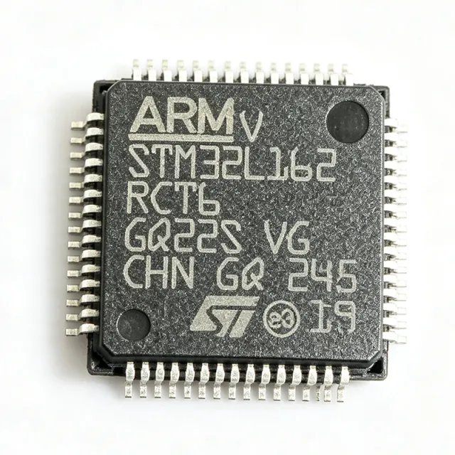
STM32L162RCT6
✓ In Stock
$2.8636 / Unit
View Datasheet →STM32L151RCT6
📋 Reference alternative (not in catalog)
STM32L100R8T6
📋 Reference alternative (not in catalog)
STM32L100RBT6
📋 Reference alternative (not in catalog)
STM32L151R8T6
📋 Reference alternative (not in catalog)
STM32L151RBT6
📋 Reference alternative (not in catalog)
STM32L152RCT6
📋 Reference alternative (not in catalog)
LPC1768FBD64
📋 Reference alternative (not in catalog)
MSP430F5438AIPZR
📋 Reference alternative (not in catalog)
STM32L100RCT6 Maximum Ratings & Electrical Characteristics
| Core | ARM Cortex-M3 |
| Max Frequency | 32 MHz |
| Flash Memory | 256 KB |
| SRAM | 16 KB |
| Supply Voltage | 1.8 V to 3.6 V |
| Package | LQFP64 |
| Operating Temperature | -40°C to +85°C |
| Low-Power Run Mode | 5.1 µA (typical) |
| Sleep Mode | 3.4 µA (typical) |
| Stop Mode | 1.8 µA (typical) |
| Standby Mode | 0.4 µA (typical) |
| ADC Resolution | 12-bit |
| ADC Channels | 16 |
| DAC Resolution | 12-bit |
| RTC | Yes (with calendar and alarm) |
| DMA | Yes |
| GPIO Pins | 51 |
| USART | 3 |
| SPI | 2 |
| I2C | 2 |
| Timers | 8 |
STM32L100RCT6 Pin Configuration
| Pin 1 | VBAT — Backup battery supply for RTC and backup registers |
| Pin 2 | PC13 — GPIO or RTC tamper pin |
| Pin 3 | PC14 — GPIO or OSC32_IN |
| Pin 4 | PC15 — GPIO or OSC32_OUT |
| Pin 5 | PF0 — GPIO or OSC_IN |
| Pin 6 | PF1 — GPIO or OSC_OUT |
| Pin 7 | NRST — Reset pin, active low |
| Pin 8 | VSSA — Analog ground |
| Pin 9 | VDDA — Analog power supply |
| Pin 10 | PA0 — GPIO or ADC input |
| Pin 11 | PA1 — GPIO or ADC input |
| Pin 12 | PA2 — GPIO or USART2_TX |
| Pin 13 | PA3 — GPIO or USART2_RX |
| Pin 14 | PA4 — GPIO or DAC_OUT1 |
| Pin 15 | PA5 — GPIO or DAC_OUT2 |
| Pin 16 | PA6 — GPIO or SPI1_MISO |
| Pin 17 | PA7 — GPIO or SPI1_MOSI |
| Pin 18 | PB0 — GPIO or ADC input |
| Pin 19 | PB1 — GPIO or ADC input |
| Pin 20 | PB2 — GPIO or BOOT1 |
| Pin 21 | PB10 — GPIO or I2C2_SCL |
| Pin 22 | PB11 — GPIO or I2C2_SDA |
| Pin 23 | PB12 — GPIO or SPI2_NSS |
| Pin 24 | PB13 — GPIO or SPI2_SCK |
| Pin 25 | PB14 — GPIO or SPI2_MISO |
| Pin 26 | PB15 — GPIO or SPI2_MOSI |
| Pin 27 | PC6 — GPIO or TIM3_CH1 |
| Pin 28 | PC7 — GPIO or TIM3_CH2 |
| Pin 29 | PC8 — GPIO or TIM3_CH3 |
| Pin 30 | PC9 — GPIO or TIM3_CH4 |
| Pin 31 | PA8 — GPIO or MCO |
| Pin 32 | PA9 — GPIO or USART1_TX |
| Pin 33 | PA10 — GPIO or USART1_RX |
| Pin 34 | PA11 — GPIO or USART1_CTS |
| Pin 35 | PA12 — GPIO or USART1_RTS |
| Pin 36 | PA13 — GPIO or SWDIO |
| Pin 37 | PA14 — GPIO or SWCLK |
| Pin 38 | PA15 — GPIO or JTDI |
| Pin 39 | PB3 — GPIO or JTDO |
| Pin 40 | PB4 — GPIO or NJTRST |
| Pin 41 | PB5 — GPIO or I2C1_SMBA |
| Pin 42 | PB6 — GPIO or I2C1_SCL |
| Pin 43 | PB7 — GPIO or I2C1_SDA |
| Pin 44 | BOOT0 — Boot mode selection |
| Pin 45 | PB8 — GPIO or CAN_RX |
| Pin 46 | PB9 — GPIO or CAN_TX |
| Pin 47 | VSS — Ground |
| Pin 48 | VDD — Power supply |
| Pin 49 | PC10 — GPIO or USART3_TX |
| Pin 50 | PC11 — GPIO or USART3_RX |
| Pin 51 | PC12 — GPIO or USART3_CK |
| Pin 52 | PD2 — GPIO or TIM3_ETR |
| Pin 53 | PB0 — GPIO or ADC input |
| Pin 54 | PB1 — GPIO or ADC input |
| Pin 55 | PB2 — GPIO or BOOT1 |
| Pin 56 | PB10 — GPIO or I2C2_SCL |
| Pin 57 | PB11 — GPIO or I2C2_SDA |
| Pin 58 | PB12 — GPIO or SPI2_NSS |
| Pin 59 | PB13 — GPIO or SPI2_SCK |
| Pin 60 | PB14 — GPIO or SPI2_MISO |
| Pin 61 | PB15 — GPIO or SPI2_MOSI |
| Pin 62 | PC6 — GPIO or TIM3_CH1 |
| Pin 63 | PC7 — GPIO or TIM3_CH2 |
| Pin 64 | PC8 — GPIO or TIM3_CH3 |
Safe Operating Area (SOA) & Thermal Characteristics
No official SOA curve available for this digital IC. Always operate within absolute maximum ratings specified in the datasheet. Ensure adequate cooling and derate as needed.
Typical Applications
STM32L100RCT6 is suitable for 6 applications: Battery-Powered Sensor Nodes, Portable Medical Devices, Smart Meters, Industrial Control Systems, Wearable Devices, Wireless Sensor Networks.
Battery-Powered Sensor Nodes
The STM32L100RCT6 is ideal for battery-powered sensor nodes due to its ultra-low-power modes (standby 0.4 µA) and wide supply voltage range (1.8V-3.6V). In a typical wireless sensor node, the MCU wakes up periodically to read sensors, process data, and transmit via a radio module, then returns to standby. The low-power run mode at 5.1 µA allows continuous sensing with minimal energy consumption. The 12-bit ADC with 16 channels can interface with various analog sensors, while the DMA controller enables efficient data transfer without CPU intervention, further reducing power. The RTC with calendar and alarm functions can schedule wake-ups, ensuring the node spends most of its time in standby. Compared to higher-power MCUs, the STM32L100RCT6 can extend battery life from months to years, making it a preferred choice for environmental monitoring, smart agriculture, and industrial IoT applications.
Recommended
Portable Medical Devices
The STM32L100RCT6 is well-suited for portable medical devices such as glucose meters, pulse oximeters, and wearable health monitors. Its ultra-low-power operation is critical for battery-powered devices that must operate for extended periods. The 12-bit ADC can accurately digitize signals from biosensors, while the DAC can generate analog outputs for calibration or stimulation. The device's low-power modes allow it to remain in standby between measurements, preserving battery life. The wide operating temperature range (-40°C to +85°C) ensures reliable operation in various environments. The Cortex-M3 core provides sufficient processing power for signal processing algorithms, such as heart rate calculation or blood oxygen saturation estimation. The rich peripheral set, including USART, SPI, and I2C, enables communication with external sensors and displays. The STM32L100RCT6's small LQFP64 package allows for compact PCB designs, essential for wearable devices.
Recommended
Smart Meters
The STM32L100RCT6 is an excellent choice for smart meters, including electricity, water, and gas meters. These devices require long-term reliability and low power consumption, as they are often battery-powered and expected to operate for years without maintenance. The MCU's ultra-low-power modes, particularly standby at 0.4 µA, ensure minimal energy drain when not actively measuring. The 12-bit ADC can accurately measure analog signals from current and voltage sensors, while the RTC provides accurate time-stamping for usage data. The device's multiple communication interfaces (USART, SPI, I2C) allow connection to communication modules for remote data transmission. The 256 KB Flash memory provides ample space for data logging and firmware updates. The wide operating temperature range ensures reliable operation in outdoor environments. The STM32L100RCT6's low power consumption and robust feature set make it a cost-effective solution for smart metering applications.
Recommended
Industrial Control Systems
The STM32L100RCT6 is suitable for industrial control systems that require reliable operation in harsh environments. Its wide operating temperature range (-40°C to +85°C) and robust design make it suitable for factory automation, process control, and building automation. The device's multiple timers and PWM outputs can control motors, actuators, and lighting systems. The 12-bit ADC can monitor analog sensors for temperature, pressure, and flow. The USART, SPI, and I2C interfaces enable communication with industrial networks such as Modbus, CAN, and Ethernet (via external transceivers). The Cortex-M3 core provides sufficient processing power for control algorithms and data processing. The low-power modes are beneficial for energy-efficient operation, especially in battery-backed or energy-harvesting systems. The STM32L100RCT6's rich peripheral set and industrial-grade reliability make it a versatile choice for various industrial applications.
Recommended
Wearable Devices
The STM32L100RCT6 is ideal for wearable devices such as fitness trackers, smartwatches, and health monitors. Its ultra-low-power consumption is essential for devices that are worn continuously and rely on small batteries. The standby current of 0.4 µA allows the device to remain in sleep mode for extended periods, waking up only to process sensor data or user interactions. The 12-bit ADC can interface with accelerometers, gyroscopes, and heart-rate sensors. The DAC can generate audio signals for alerts or feedback. The device's small LQFP64 package enables compact and lightweight designs. The Cortex-M3 core provides enough processing power for real-time sensor fusion and activity recognition algorithms. The multiple communication interfaces (I2C, SPI, USART) allow connection to Bluetooth Low Energy modules for smartphone connectivity. The STM32L100RCT6's combination of low power, small size, and rich peripherals makes it a popular choice for wearable technology.
Recommended
Wireless Sensor Networks
The STM32L100RCT6 is well-suited for wireless sensor networks (WSNs) where nodes are deployed in remote locations and must operate on battery power for years. Its ultra-low-power modes, including standby at 0.4 µA, are critical for maximizing battery life. The device can wake up periodically to read sensors, process data, and transmit via a radio module, then return to sleep. The 12-bit ADC with 16 channels can interface with various sensors, while the DMA controller enables efficient data transfer without CPU intervention, reducing power consumption. The RTC can schedule wake-ups, ensuring precise timing for data collection. The device's multiple communication interfaces (USART, SPI, I2C) allow connection to various radio modules, such as LoRa, Zigbee, or sub-GHz transceivers. The 256 KB Flash memory provides ample space for data logging and over-the-air updates. The STM32L100RCT6's low power consumption and robust feature set make it an excellent choice for WSN applications.
Recommended
Recommended Products Summary
Engineering reference data for STM32L100RCT6 — comparison, design guidance, and compliance information.
Selection Guide
Comparison with Alternatives
| Parameter | This Product | STM32L151RCT6 | STM32L100R8T6 | STM32L100RBT6 | STM32L151R8T6 | STM32L151RBT6 | STM32L152RCT6 | STM32L162RCT6 | LPC1768FBD64 |
|---|---|---|---|---|---|---|---|---|---|
| Package | LQFP64 | LQFP64 | LQFP64 | LQFP64 | LQFP64 | LQFP64 | LQFP64 | LQFP64 | LQFP64 |
| Brand | STMicroelectronics | STMicroelectronics | STMicroelectronics | STMicroelectronics | STMicroelectronics | STMicroelectronics | STMicroelectronics | STMicroelectronics | NXP Semiconductors |
| Core | ARM Cortex-M3 | ARM Cortex-M3 | ARM Cortex-M3 | ARM Cortex-M3 | ARM Cortex-M3 | ARM Cortex-M3 | ARM Cortex-M3 | ARM Cortex-M3 | ARM Cortex-M3 |
| Max Frequency | 32 MHz | 32 MHz | 32 MHz | 32 MHz | 32 MHz | 32 MHz | 32 MHz | 32 MHz | 100 MHz |
| Flash Memory | 256 KB | 256 KB | 64 KB | 128 KB | 64 KB | 128 KB | 256 KB | 256 KB | 512 KB |
| SRAM | 16 KB | 16 KB | 8 KB | 16 KB | 16 KB | 16 KB | 16 KB | 16 KB | 64 KB |
| Standby Current | 0.4 µA | 0.4 µA | 0.4 µA | 0.4 µA | 0.4 µA | 0.4 µA | 0.4 µA | 0.4 µA | 2.5 µA |
| ADC Resolution | 12-bit | 12-bit | 12-bit | 12-bit | 12-bit | 12-bit | 12-bit | 12-bit | 12-bit |
| DAC Resolution | 12-bit | 12-bit | 12-bit | 12-bit | 12-bit | 12-bit | 12-bit | 12-bit | None |
Key Differentiators
- Ultra-low standby current of 0.4 µA (vs LPC1768FBD64)
- Integrated 12-bit DAC (vs LPC1768FBD64)
- Pin-compatible with higher-performance STM32L1 family (vs STM32L151RCT6)
Design Notes
For optimal power consumption, use the low-speed internal oscillator (LSI) for the RTC and configure unused GPIOs to analog mode to reduce leakage. In standby mode, ensure all I/Os are properly configured to avoid floating inputs. Use the PWR_EnterSTANDBYMode function to enter standby, and configure wake-up sources such as the RTC alarm or external interrupts. The typical standby current is 0.4 µA, but this can increase if GPIOs are not properly set. Refer to the STM32L100xx datasheet and application note AN3193 for detailed low-power design guidelines.
Place a 100 nF decoupling capacitor close to each VDD pin and a 1 µF capacitor on the VDDA pin. Use a ground plane to minimize noise and ensure stable operation. For the crystal oscillator, place the crystal and load capacitors as close as possible to the OSC_IN and OSC_OUT pins, and keep the trace lengths short to reduce parasitic capacitance. Follow the layout recommendations in the STM32L100xx datasheet and application note AN2867 for oscillator design.
Avoid exceeding the absolute maximum ratings, particularly the supply voltage (VDD) which must not exceed 3.6V. Ensure the BOOT0 pin is properly configured to select the correct boot mode; a floating BOOT0 can cause unexpected boot behavior. When using the ADC, ensure the VDDA pin is properly decoupled and the reference voltage is stable. Also, be aware that the STM32L100RCT6 does not have a true EEPROM; if you need non-volatile data storage, consider using the STM32L151RCT6 which includes a true EEPROM.
Compliance Information
RoHS and REACH compliant per STMicroelectronics product page. Not AEC-Q100 qualified. Halogen-free status not specified in provided data.