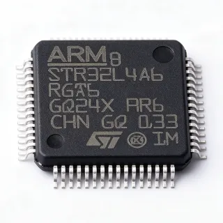
STM32L562RET6 - 512KB Flash, 110MHz Cortex-M33 MCU | STMicroelectronics
MPN: STM32L562RET6 ✓ Active| Qty | Unit Price | Extended |
|---|---|---|
| 1 | $8.5 | $8.50 |
| 10 | $7.65 | $76.50 |
| 100 | $6.8 | $680.00 |
| 500 | $6.12 | $3,060.00 |
| 1,000 | $5.44 | $5,440.00 |
Drop-in alternatives for STM32L562RET6 — same package, pin-to-pin compatible. Different-package parts requiring PCB rework are excluded.
Quick Comparison Tool — Select alternative parts for side-by-side comparison:
STM32L562RET6TR
✅ Drop-In📋 Reference alternative (not in catalog)
STM32L562RET6Q
✅ Drop-In📋 Reference alternative (not in catalog)
STM32L562RET6V
✅ Drop-In📋 Reference alternative (not in catalog)
STM32L552RET6
✅ Drop-In✓ In Stock
$5.48 / Unit
View Datasheet →STM32L562REI6
✅ Drop-In📋 Reference alternative (not in catalog)
STM32L562RET6 Maximum Ratings & Electrical Characteristics
| Core | Arm Cortex-M33 with TrustZone |
| Maximum Clock Frequency | 110 MHz |
| Flash Memory | 512 KB |
| SRAM | 256 KB |
| Package | 64-LQFP (10x10 mm) |
| Supply Voltage Range | 1.71 V to 3.6 V |
| Operating Temperature Range | -40C to +85C |
| Standby Current | 100 nA |
| ADC Resolution | 12-bit |
| Number of I/O Pins | [DATA_NEEDED: Number of I/O pins] |
| Communication Interfaces | UART, SPI, I2C, USB |
| Cryptographic Accelerator | AES, RSA, ECC |
| True Random Number Generator | Yes |
| Process Technology | 40 nm |
| RoHS Status | Compliant |
STM32L562RET6 Pin Configuration
| Pin 1 | VBAT — Battery backup supply |
| Pin 2 | PC13 — GPIO / RTC output |
| Pin 3 | PC14 — GPIO / OSC32_IN |
| Pin 4 | PC15 — GPIO / OSC32_OUT |
| Pin 5 | PF0 — GPIO |
| Pin 6 | PF1 — GPIO |
| Pin 7 | NRST — Reset |
| Pin 8 | VDD — Digital power supply |
| Pin 9 | VSS — Ground |
| Pin 10 | VDDA — Analog power supply |
| Pin 11 | PA0 — GPIO / ADC input |
| Pin 12 | PA1 — GPIO / ADC input |
| Pin 13 | PA2 — GPIO / USART2_TX |
| Pin 14 | PA3 — GPIO / USART2_RX |
| Pin 15 | PA4 — GPIO / SPI1_NSS |
| Pin 16 | PA5 — GPIO / SPI1_SCK |
| Pin 17 | PA6 — GPIO / SPI1_MISO |
| Pin 18 | PA7 — GPIO / SPI1_MOSI |
| Pin 19 | PA8 — GPIO / USB_OTG_FS_SOF |
| Pin 20 | PA9 — GPIO / USART1_TX |
| Pin 21 | PA10 — GPIO / USART1_RX |
| Pin 22 | PA11 — GPIO / USB_DM |
| Pin 23 | PA12 — GPIO / USB_DP |
| Pin 24 | PA13 — GPIO / SWDIO |
| Pin 25 | PA14 — GPIO / SWCLK |
| Pin 26 | PA15 — GPIO / JTDI |
| Pin 27 | PB0 — GPIO / ADC input |
| Pin 28 | PB1 — GPIO / ADC input |
| Pin 29 | PB2 — GPIO / BOOT1 |
| Pin 30 | PB3 — GPIO / JTDO |
| Pin 31 | PB4 — GPIO / NJTRST |
| Pin 32 | PB5 — GPIO / I2C1_SMBA |
| Pin 33 | PB6 — GPIO / I2C1_SCL |
| Pin 34 | PB7 — GPIO / I2C1_SDA |
| Pin 35 | PB8 — GPIO / I2C1_SCL |
| Pin 36 | PB9 — GPIO / I2C1_SDA |
| Pin 37 | PB10 — GPIO / I2C2_SCL |
| Pin 38 | PB11 — GPIO / I2C2_SDA |
| Pin 39 | PB12 — GPIO / SPI2_NSS |
| Pin 40 | PB13 — GPIO / SPI2_SCK |
| Pin 41 | PB14 — GPIO / SPI2_MISO |
| Pin 42 | PB15 — GPIO / SPI2_MOSI |
| Pin 43 | PC0 — GPIO / ADC input |
| Pin 44 | PC1 — GPIO / ADC input |
| Pin 45 | PC2 — GPIO / ADC input |
| Pin 46 | PC3 — GPIO / ADC input |
| Pin 47 | PC4 — GPIO / ADC input |
| Pin 48 | PC5 — GPIO / ADC input |
| Pin 49 | PC6 — GPIO / TIM3_CH1 |
| Pin 50 | PC7 — GPIO / TIM3_CH2 |
| Pin 51 | PC8 — GPIO / TIM3_CH3 |
| Pin 52 | PC9 — GPIO / TIM3_CH4 |
| Pin 53 | PC10 — GPIO / USART3_TX |
| Pin 54 | PC11 — GPIO / USART3_RX |
| Pin 55 | PC12 — GPIO / USART3_CK |
| Pin 56 | PD0 — GPIO / OSC_IN |
| Pin 57 | PD1 — GPIO / OSC_OUT |
| Pin 58 | PD2 — GPIO / TIM1_ETR |
| Pin 59 | PD3 — GPIO / USART2_CTS |
| Pin 60 | PD4 — GPIO / USART2_RTS |
| Pin 61 | PD5 — GPIO / USART2_TX |
| Pin 62 | PD6 — GPIO / USART2_RX |
| Pin 63 | PD7 — GPIO / USART2_CK |
| Pin 64 | VDD — Digital power supply |
Safe Operating Area (SOA) & Thermal Characteristics
No official SOA curve available for this digital IC. Always operate within absolute maximum ratings specified in the datasheet. Ensure adequate cooling and derate as needed.
Typical Applications
STM32L562RET6 is suitable for 6 applications: Secure IoT Nodes, Smart Meters, Wearable Health Monitors, Industrial Sensors, Battery-Powered Medical Devices, Smart Home Controllers.
Secure IoT Nodes
The STM32L562RET6 is ideal for secure IoT nodes due to its ultra-low power consumption, TrustZone security, and hardware cryptographic accelerator. These features enable secure communication and data protection in edge devices. In a typical IoT node, the MCU collects sensor data, encrypts it using the AES accelerator, and transmits it via a low-power wireless interface. The standby current of 100 nA ensures long battery life, while the Cortex-M33 core provides sufficient processing power for protocol stacks and edge processing. Designers should configure the low-power modes and use the RTC for periodic wake-ups to maximize battery life.
Recommended
Smart Meters
The STM32L562RET6 is well-suited for smart meters, where accurate measurement, secure communication, and low power are essential. The 12-bit ADC provides precise analog measurements for current and voltage sensing, while the cryptographic accelerator ensures secure data transmission to the utility grid. The MCU's low-power modes allow it to operate on battery backup during power outages. In a typical smart meter, the STM32L562RET6 reads sensor data, processes it, and communicates via a wireless module. The TrustZone security isolates metering firmware from communication stacks, preventing tampering. Designers should use the internal RTC for time-stamping and schedule periodic data uploads to minimize power consumption.
Recommended
Wearable Health Monitors
The STM32L562RET6 is an excellent choice for wearable health monitors, offering ultra-low power consumption and secure data handling. The MCU can process biometric signals from sensors like heart rate monitors and accelerometers, while the TrustZone security protects patient data. The 100 nA standby current allows the device to operate for extended periods on a small battery. In a typical wearable, the STM32L562RET6 collects sensor data, runs signal processing algorithms, and communicates via Bluetooth Low Energy. The FPU accelerates math-intensive operations like filtering and feature extraction. Designers should optimize the firmware to use the low-power modes and minimize active time to extend battery life.
Recommended
Industrial Sensors
The STM32L562RET6 is suitable for industrial sensors that require reliable operation in harsh environments. The wide operating temperature range (-40°C to +85°C) and robust communication interfaces make it ideal for factory automation and process control. The MCU can interface with various industrial protocols like Modbus and CAN, while the cryptographic accelerator ensures secure data exchange. In a typical industrial sensor, the STM32L562RET6 reads analog signals, processes them, and transmits data over a fieldbus. The low-power modes reduce energy consumption in battery-powered wireless sensors. Designers should implement proper ESD protection and use the internal watchdog timer for system reliability.
Recommended
Battery-Powered Medical Devices
The STM32L562RET6 is well-suited for battery-powered medical devices, offering ultra-low power consumption and advanced security features. The MCU can handle complex algorithms for patient monitoring while maintaining data integrity through TrustZone. The 100 nA standby current is critical for devices that must operate for months or years on a single battery. In a typical medical device, the STM32L562RET6 processes sensor data, stores it in flash, and communicates with a base station. The cryptographic accelerator ensures secure data transmission, complying with healthcare regulations. Designers should use the low-power modes and implement a robust power management strategy to maximize battery life.
Recommended
Smart Home Controllers
The STM32L562RET6 is an ideal choice for smart home controllers, providing secure and efficient management of connected devices. The MCU can handle multiple communication protocols like Zigbee, Z-Wave, and Wi-Fi, while the TrustZone security protects the home network from cyber threats. The low-power modes allow the controller to operate on battery backup during power outages. In a typical smart home hub, the STM32L562RET6 manages device communication, runs automation rules, and provides a user interface. The cryptographic accelerator ensures secure communication with cloud services. Designers should use the internal RTC for scheduling and implement over-the-air firmware updates for security patches.
Recommended
Recommended Products Summary
Engineering reference data for STM32L562RET6 — comparison, design guidance, and compliance information.
Selection Guide
Comparison with Alternatives
| Parameter | This Product | STM32L562RET6TR | STM32L562RET6Q | STM32L562RET6V | STM32L552RET6 | STM32L562REI6 |
|---|---|---|---|---|---|---|
| Package | 64-LQFP (10x10 mm) | 64-LQFP (10x10 mm) - same | 64-LQFP (10x10 mm) - same | 64-LQFP (10x10 mm) - same | 64-LQFP (10x10 mm) - same | 64-LQFP (10x10 mm) - same |
| Brand | STMicroelectronics | STMicroelectronics | STMicroelectronics | STMicroelectronics | STMicroelectronics | STMicroelectronics |
| Core | Arm Cortex-M33 with TrustZone | Arm Cortex-M33 with TrustZone | Arm Cortex-M33 with TrustZone | Arm Cortex-M33 with TrustZone | Arm Cortex-M33 with TrustZone | Arm Cortex-M33 with TrustZone |
| Maximum Clock Frequency | 110 MHz | 110 MHz | 110 MHz | 110 MHz | 110 MHz | 110 MHz |
| Flash Memory | 512 KB | 512 KB | 512 KB | 512 KB | 512 KB | 512 KB |
| SRAM | 256 KB | 256 KB | 256 KB | 256 KB | 256 KB | 256 KB |
| Supply Voltage Range | 1.71V to 3.6V | 1.71V to 3.6V | 1.71V to 3.6V | 1.71V to 3.6V | 1.71V to 3.6V | 1.71V to 3.6V |
| Standby Current | 100 nA | 100 nA | 100 nA | 100 nA | 100 nA | 100 nA |
Key Differentiators
- TrustZone security (vs STM32L552RET6)
- Hardware cryptographic accelerator (vs STM32L552RET6)
- True random number generator (TRNG) (vs STM32L552RET6)
Design Notes
For optimal power consumption, use the low-power modes (Sleep, Stop, Standby) and configure the clock to use the low-speed internal oscillator (LSI) when high precision is not required. The standby current of 100 nA is achievable only when all peripherals are disabled and the RTC is powered by VBAT. Ensure that the firmware properly configures the power control registers to enter the desired low-power mode.
Place 100nF decoupling capacitors close to each VDD pin and a 1uF capacitor on the VDDA pin for analog noise filtering. Use a ground plane to minimize noise and ensure proper return paths for high-speed signals. For USB applications, route the USB_DM and USB_DP traces as a differential pair with controlled impedance.
Ensure that the BOOT0 pin is properly configured to select the correct boot mode. For secure applications, enable TrustZone early in the firmware development to isolate critical code. Avoid exceeding the absolute maximum ratings for supply voltage and I/O pins, as this can damage the device. Use the internal watchdog timer to prevent system hangs in industrial environments.
Compliance Information
RoHS compliant per STMicroelectronics product page. Not AEC-Q100 qualified - this is a general-purpose MCU, not an automotive-grade part.