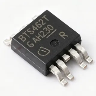
BTS452TATMA1 - 1.8A High-Side Smart Power Switch | Infineon
MPN: BTS452TATMA1 ✓ Active| Qty | Unit Price | Extended |
|---|---|---|
| 1 | $1.85 | $1.85 |
| 10 | $1.65 | $16.50 |
| 100 | $1.45 | $145.00 |
| 500 | $1.28 | $640.00 |
| 1,000 | $1.12 | $1,120.00 |
BTS452TATMA1 Overview
A high-side power switch (also called a smart high-side driver or PROFET) is an N-channel MOSFET configured between the supply rail and the load, allowing the load to be grounded and switched by pulling the MOSFET gate high. Compared with discrete MOSFETs plus fuses, an integrated high-side switch embeds protection (overcurrent, short-circuit, overtemperature, overvoltage, undervoltage) and diagnostic feedback (status flag), reducing BOM count and improving reliability in harsh electrical environments such as automotive 12 V/24 V buses.
Key features include active current limiting with restart, thermal shutdown with auto-restart, overvoltage protection including load-dump survival, undervoltage shutdown, and an open-drain status output. The BTS452TATMA1 is microcontroller-compatible, accepting 3.3 V or 5 V logic inputs directly at the IN pin. Its PG-TO252-5 (DPAK) package with exposed metal tab provides low thermal resistance (~50 C/W) for continuous 1.8 A operation without external heatsinking on moderate PCB copper area.
The BTS452TATMA1 uses Infineon's SIPMOS vertical DMOS process, providing low RDS(on) per unit silicon area and inherent avalanche ruggedness. The integrated charge pump generates the gate drive above the supply rail to fully enhance the N-channel MOSFET, while the diagnostic logic monitors drain current and die temperature. The result is a single-package solution that replaces a discrete MOSFET, gate driver, current-sense resistor, and protection circuitry.
Typical applications include automotive body electronics (lighting, seat heaters, mirror heaters, door locks), industrial 24 V load switching (solenoids, valves, small motors), and resistive/inductive/capacitive load control in PLCs and process control modules. It is qualified to AEC-Q100 standards for automotive use and is one of the most widely deployed PROFET parts in vehicle ECUs.
When designing with this device, ensure the IN pin logic levels match your microcontroller's GPIO output (TTL/CMOS compatible), route the status output to an interrupt-capable input for fault handling, and observe derating above 25 C ambient. The exposed pad must be soldered to a copper pour of at least 50 mm² for rated continuous current at 85 C ambient.
This page synthesizes distributor pricing, drop-in alternatives, and practical design notes not found in the manufacturer datasheet.
Drop-in alternatives for BTS452TATMA1 — same package, pin-to-pin compatible. Different-package parts requiring PCB rework are excluded.
Variants in this series
Same-series models that are drop-in compatible with BTS452TATMA1 (same form factor and footprint) — differing in Package, Continuous Load Current, Operating Temperature Range, Topology, Diagnostic Output.
Quick Comparison Tool — Select alternative parts for side-by-side comparison:
BTS452T
✅ Drop-In📋 Reference alternative (not in catalog)
BTS452TATMA1
✅ Drop-In✓ In Stock
$1.12 / Unit
View Datasheet →BTS452R
✅ Drop-In ⚠️ 参数待验证📋 Reference alternative (not in catalog)
BTS452E2
✅ Drop-In ⚠️ 参数待验证📋 Reference alternative (not in catalog)
BTS452C6GATMA1
✅ Drop-In📋 Reference alternative (not in catalog)
BTS452TATMA1 Maximum Ratings & Electrical Characteristics
| Part Number | BTS452TATMA1 |
| Manufacturer | Infineon Technologies |
| Product Family | MINI-PROFET (Smart High-Side Power Switch) |
| Switch Type | High-Side, N-Channel |
| Number of Outputs | 1 |
| Supply Voltage (Operating) | 6 V to 52 V |
| Continuous Load Current | 1.8 A |
| On-State Resistance (RDS(on)) | 200 mOhm (typical) |
| Input Logic Level | TTL/CMOS compatible |
| Operating Temperature | -40 C to +150 C junction |
| Package | PG-TO252-5 (DPAK-5) |
| Mounting Type | Surface Mount |
| Status Output | Open-drain diagnostic flag |
| Protection Features | Overcurrent, Short-circuit, Thermal shutdown with restart, Overvoltage (load dump), Undervoltage shutdown |
| Automotive Qualification | AEC-Q100 qualified |
| Technology | SIPMOS vertical DMOS with charge pump |
| RoHS Status | Compliant |
BTS452TATMA1 Pin Configuration
| Pin 1 | IN — Logic input (TTL/CMOS compatible, active high turns switch on) |
| Pin 2 | GND — Ground reference |
| Pin 3 | ST — Status output (open drain; pulls low on fault) |
| Pin 4 | Vbb — Supply voltage (6 V to 52 V operating range) |
| Pin 5 | OUT — Switched output to load |
Typical Applications
BTS452TATMA1 is suitable for 7 applications: Automotive Lighting Load Switching, Automotive Body Electronics - Heated Seats & Mirrors, Industrial 24 V Solenoid & Valve Control, Relay & Contactor Replacement, DC Motor Control (Small Brushed Motors), LED Driver Module (Automotive Interior), PLC Digital Output Module.
Automotive Lighting Load Switching
The BTS452TATMA1 is purpose-built for automotive 12 V lighting loads including headlights, tail lights, turn signals, and interior illumination. Its 52 V overvoltage rating survives 24 V jump-start events and load-dump transients up to the AEC-Q100 specification, while the 1.8 A continuous rating comfortably drives a 21 W incandescent bulb or multiple parallel LED strings with appropriate current limiting. The integrated thermal shutdown with auto-restart protects against the inrush current of cold filament bulbs, which can reach 10x steady-state for tens of milliseconds. The status output lets the body-control module detect open-circuit (bulb burned out) or short-circuit (wiring fault) conditions, enabling OBD-II diagnostic reporting. Compared with a discrete MOSFET plus fuse, the BTS452TATMA1 eliminates the fuse-replacement service issue and provides software-controlled fault recovery.
Recommended
Automotive Body Electronics - Heated Seats & Mirrors
Body electronics modules use the BTS452TATMA1 to drive resistive heating elements in seats, mirrors, and steering wheels where the 1.8 A current rating matches typical 12 V heating pad draws of 15-20 W. The device's PG-TO252-5 package dissipates approximately 1 W of conduction loss (I²R = 1.8² × 200 mOhm) at full load, easily handled by a small copper pour on the PCB without external heatsinking. The TTL-compatible IN pin connects directly to a microcontroller GPIO, while the ST pin provides fault feedback to the BCM for diagnostic trouble codes (DTCs) per UDS protocol. The BTS452TATMA1's undervoltage shutdown prevents seat-heater operation during engine cranking when battery voltage sags below 6 V, avoiding unreliable PWM regulation in brownout conditions.
Recommended
Industrial 24 V Solenoid & Valve Control
In industrial 24 V DC control panels, the BTS452TATMA1 drives hydraulic solenoid valves, pneumatic actuators, and small relays where its 52 V rating provides headroom over the nominal 24 V rail plus inductive kick transients. The integrated active current limiting and short-circuit protection are essential when driving solenoids, whose inrush current can be 5-10x holding current and which are prone to short-to-ground faults from mechanical wear. The 200 mOhm RDS(on) keeps conduction losses manageable even at the 1.8 A continuous limit, allowing the device to be mounted on a DIN-rail PCB without active cooling. The diagnostic status pin connects to a PLC digital input for closed-loop fault detection in process control loops.
Recommended
Relay & Contactor Replacement
The BTS452TATMA1 is increasingly used as a solid-state replacement for automotive and industrial electromechanical relays in applications where its 1.8 A current limit is sufficient. Compared with a 12 V automotive relay (typically rated 30-40 A), the BTS452TATMA1 trades raw current capacity for diagnostic feedback, silent operation, and elimination of mechanical bounce and contact welding. The 200 mOhm RDS(on) yields a voltage drop of 360 mV at full load, slightly higher than a closed relay contact but acceptable for most loads. Designers gain PWM capability (the BTS452TATMA1 can be switched at up to several kHz) for applications like soft-start, dimming, or proportional control that electromechanical relays cannot provide.
Recommended
DC Motor Control (Small Brushed Motors)
Small brushed DC motors in automotive applications (window lifts, mirror adjusters, seat positioners) operate well within the BTS452TATMA1's 1.8 A envelope. The device's integrated short-circuit protection handles motor stall conditions where current can spike to 5-10x running current, and the thermal shutdown with auto-restart allows recovery once the motor un-stalls. Direction reversal can be achieved with an H-bridge using two BTS452TATMA1 high-side switches plus two low-side N-MOSFETs. The PG-TO252-5 package handles the regenerative braking energy of small motors during PWM deceleration. Note that for motors above 2 A continuous, designers should consider the higher-current BTS452C6 family in a larger package.
Recommended
LED Driver Module (Automotive Interior)
Interior LED modules for ambient lighting, dashboard backlights, and indicator lamps benefit from the BTS452TATMA1's clean PWM switching capability and fault diagnostic output. The device switches at frequencies up to several kHz with low propagation delay, enabling smooth dimming via direct microcontroller PWM without visible flicker. The 200 mOhm RDS(on) keeps conduction losses low even at 1 A of LED string current, and the integrated short-circuit protection prevents damage if an LED string fails short. The ST pin reports open-circuit (LED string failure) and short-circuit (wiring fault) conditions to the BCM for diagnostic logging, supporting ISO 14229 UDS services.
Recommended
PLC Digital Output Module
Programmable Logic Controller (PLC) digital output modules use the BTS452TATMA1 to provide 24 V DC switching for industrial field devices such as indicator lamps, small solenoid valves, and sensor power supplies. The 52 V maximum rating covers 24 V industrial bus voltage plus transient surges, and the 1.8 A continuous output supports most PLC DO channel requirements. The TTL-compatible input interfaces directly with the PLC's 3.3 V or 5 V logic, eliminating level-shifter circuitry. The diagnostic status output can be routed to the PLC's input section to report field-side faults back to the controller, supporting predictive maintenance and IEC 61131-3 fault-handling routines.
Recommended
Recommended Products Summary
Engineering reference data for BTS452TATMA1 — comparison, design guidance, and compliance information.
Selection Guide
Comparison with Alternatives
| Parameter | This Product | BTS452T | BTS452R | BTS452E2 | BTS452C6GATMA1 |
|---|---|---|---|---|---|
| Brand | Infineon | Infineon | Infineon | Infineon | Infineon |
| Package | PG-TO252-5 (DPAK-5) | PG-TO252-5 (DPAK-5) - same | PG-TO252-5 (DPAK-5) - same | PG-TO252-5 (DPAK-5) - same | PG-TO252-5 (DPAK-5) - same |
| Continuous Load Current | 1.8 A | 1.8 A | 1.8 A | 1.6 A | 3 A (estimated, based on family) |
| Supply Voltage (Operating) | 6 V to 52 V | 6 V to 52 V | 6 V to 52 V | 6 V to 52 V | 6 V to 52 V |
| Logic Input Compatibility | TTL/CMOS (3.3 V and 5 V) | TTL/CMOS | TTL/CMOS | TTL/CMOS | TTL/CMOS |
| Status Output | Yes (open drain) | Yes | Yes | Yes | Yes |
| AEC-Q100 Qualification | Qualified | Qualified | Qualified | Qualified | Qualified |
| Thermal Shutdown with Restart | Yes | Yes | Yes | Yes | Yes |
Key Differentiators
- AEC-Q100 qualified with 52 V load-dump survival (vs Discrete N-MOSFET + fuse designs)
- Diagnostic status output for OBD-II fault reporting (vs BTS452R (same family, similar RDS(on)))
- Optimized 1.8 A / 200 mOhm sweet spot for 12 V body loads (vs BTS452C6GATMA1 (higher current, larger package))
Design Notes
Estimated: At full 1.8 A load and 12 V supply, conduction loss is I²R = 1.8² × 0.2 = 0.65 W. With PG-TO252-5 thermal resistance of approximately 50 C/W on the minimum recommended footprint (50 mm² copper), junction temperature rise above ambient is 0.65 W × 50 C/W = 32.5 C. For continuous operation at 85 C ambient, the junction reaches ~118 C - within the 150 C rating but with limited margin. Increase PCB copper area to 100 mm² for derated operation above 1.5 A in high-ambient environments.
The exposed metal tab of the PG-TO252-5 package is internally connected to Vbb (the supply pin) and must be soldered to a copper pour on the PCB. This serves dual purposes: thermal dissipation and electrical connection to the high-current supply rail. Use multiple thermal vias under the tab to the opposite PCB layer to maximize heat transfer. The IN, GND, ST, and OUT traces should be kept short to minimize parasitic inductance, particularly on the OUT pin where load-side transients couple back to the die.
Do not leave the ST (status) pin floating if not used; it is an open-drain output that requires an external pull-up resistor (typically 10 kOhm to 5 V) to function correctly. Floating ST pins can cause false fault indications. Also note that the device includes a restart delay after thermal shutdown - do not interpret the momentary switch-off as a permanent fault. The IN pin is TTL/CMOS compatible and accepts 3.3 V logic directly, but signals above Vbb may cause input current injection; clamp if necessary.
Route the high-current OUT trace with wide copper (at least 1 mm wide per 100 mA, or use a copper pour) to handle the 1.8 A without significant voltage drop. Place the BTS452TATMA1 close to the connector or load to minimize the switched-current loop area, which reduces EMI radiated emissions. The GND pin should be connected to the system ground plane with a via or short trace; do not daisy-chain ground through the load ground return path.
Compliance Information
RoHS and REACH compliance per Infineon product page. AEC-Q100 qualified for automotive applications. Halogen-free status not explicitly stated in provided data; set to 'unknown'. Conflict-minerals compliance per Infineon's standard CMRT declarations.