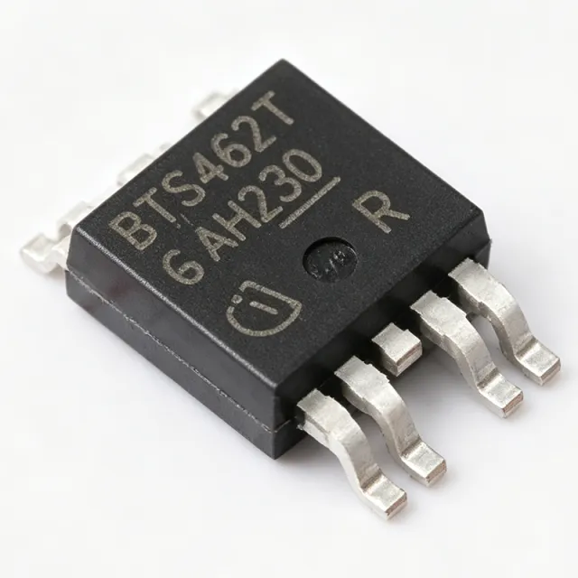
BTS462TATMA1 - 3.5A Smart High-Side Power Switch | Infineon
MPN: BTS462TATMA1 ✓ Active| Qty | Unit Price | Extended |
|---|---|---|
| 1 | $2.18 | $2.18 |
| 10 | $1.96 | $19.60 |
| 100 | $1.74 | $174.00 |
| 500 | $1.55 | $775.00 |
| 1,000 | $1.38 | $1,380.00 |
BTS462TATMA1 Overview
A smart high-side power switch is a semiconductor relay that places the load between ground and the switch output, allowing the IC to drive resistive, capacitive, and inductive loads with controlled turn-on/turn-off. High-side switches sit in the power management IC hierarchy above simple MOSFET drivers and below multi-channel system basis chips, providing per-channel protection against the most common fault modes encountered in automotive wiring (short-to-ground, overload, load-dump, and reverse-battery events).
Key specifications include a continuous drain current of 3.5 A, an on-state resistance (RDS(on)) typically around 50 mOhm at 25 C, current-limit trip near 7 A, and built-in thermal shutdown with auto-restart. The device also features overvoltage protection covering load-dump transients, undervoltage shutdown to prevent in-rush faults, fast demagnetization for inductive loads, and a diagnostic feedback pin that signals open-load and overtemperature conditions back to the host microcontroller.
Architecturally, the BTS462TATMA1 uses a vertical N-channel DMOS output stage driven by a CMOS charge-pump and logic interface, all co-integrated on a single die. The charge-pump maintains the gate drive above the source rail, ensuring low RDS(on) regardless of battery voltage. This monolithic integration delivers far better protection coverage than a discrete MOSFET plus fuse approach while reducing PCB footprint.
Typical applications include automotive body controllers driving lamps, solenoids, and DC motors; industrial PLC discrete output modules; HVAC actuators; and any 12 V/24 V load that requires embedded protection. The PG-TO252-5 package provides a thermal pad that, when properly soldered to a copper pour, enables sustained 3.5 A operation without a heatsink.
When designing with the BTS462TATMA1, observe input capacitor placement (close to Vbb pin) and a generous copper area on the drain tab to limit junction temperature rise. Fault-flag interpretation should be debounced in software, as the STATUS pin can pulse during legitimate switching transients.
This page consolidates distributor pricing, cross-brand drop-in equivalents, and practical protection-circuit notes that extend beyond the manufacturer datasheet's typical application example.
Drop-in alternatives for BTS462TATMA1 — same package, pin-to-pin compatible. Different-package parts requiring PCB rework are excluded.
Variants in this series
Same-series models that are drop-in compatible with BTS462TATMA1 (same form factor and footprint) — differing in Package, Product Type, Automotive Qualification, Operating Temperature, Protection Features.
Quick Comparison Tool — Select alternative parts for side-by-side comparison:
BTS452RATMA1
✓ In Stock
$0.85 / Unit
View Datasheet →BTS6143DAUMA1
✓ In Stock
$1.21 / Unit
View Datasheet →BTS6133DAUMA1
✓ In Stock
$1.98 / Unit
View Datasheet →BTS5014SDAAUMA1
✓ In Stock
$1.55 / Unit
View Datasheet →BSP78HUMA1
✓ In Stock
$0.62 / Unit
View Datasheet →ITS4200SMEPHUMA1
✓ In Stock
$0.86 / Unit
View Datasheet →BTS462TATMA1 Maximum Ratings & Electrical Characteristics
| Manufacturer | Infineon Technologies |
| Product Type | Smart High-Side Power Switch |
| Number of Channels | 1 |
| Output Configuration | High-Side |
| Output Current (Continuous) | 3.5 A |
| Supply Voltage Range (Vbb) | 5 V to 34 V |
| Load Dump Protection | Yes |
| Overvoltage Protection | Yes |
| Overload / Current Limit | Yes |
| Short-Circuit Protection | Yes |
| Thermal Shutdown | Yes (with auto-restart) |
| Undervoltage Shutdown | Yes |
| Fast Demagnetization | Yes (for inductive loads) |
| Diagnostic Output (STATUS pin) | Yes |
| Operating Temperature | -40 C to +150 C (junction) |
| Package | PG-TO252-5 (DPAK-5) |
| Mounting Type | Surface Mount |
| RoHS Status | Compliant |
BTS462TATMA1 Pin Configuration
| Pin 1 | OUT — Power output to load (also exposed tab) |
| Pin 2 | Vbb — Battery / supply voltage input (5 V to 34 V) |
| Pin 3 | GND — Logic and power ground |
| Pin 4 | IN — Logic input (TTL/CMOS compatible, drives gate) |
| Pin 5 | STATUS — Diagnostic output (open-drain fault flag) |
Typical Applications
BTS462TATMA1 is suitable for 6 applications: Automotive Body Control Modules, Industrial PLC Discrete Outputs, HVAC Actuator and Valve Drivers, LED Lighting Modules and Drivers, Solenoid and Relay Coil Driving, Battery-Powered Equipment Load Switch.
Automotive Body Control Modules
The BTS462TATMA1 is a strong fit for automotive body control modules driving lamps, mirror heaters, and small solenoids from a 12 V battery rail. Its 5 V to 34 V supply range with integrated load-dump protection handles ISO 7637-2 transient events without external TVS components. The 3.5 A continuous current covers typical incandescent and early-LED rear-lamp loads, while the STATUS feedback pin lets the BCM microcontroller detect open-filament or short-circuit faults and illuminate a dashboard warning. The MINI-PROFET architecture also demagnetizes inductive loads like door-lock solenoids safely inside the IC, eliminating the catch diode that a discrete MOSFET design would otherwise require.
Recommended
Industrial PLC Discrete Outputs
The BTS462TATMA1 serves as the output stage for industrial PLC discrete output modules interfacing 24 V field loads. Its 34 V upper supply limit covers the 24 V nominal rail plus transient excursions, and the integrated current-limit and thermal shutdown protect the module from wiring faults in the field. Compared to a discrete MOSFET plus fuse design, the BTS462TATMA1 eliminates the fuse-replacement maintenance issue entirely, since the IC self-recovers after thermal shutdown. The PG-TO252-5 package fits standard PLC card form factors, and the exposed tab solders to the card's ground pour to dissipate the heat from continuous 24 V relay-coil driving.
Recommended
HVAC Actuator and Valve Drivers
The BTS462TATMA1 drives HVAC damper actuators, water valves, and small 24 V brushless DC fans with built-in protection against stalled-rotor conditions. The fast-demagnetization circuitry handles the back-EMF of motor windings without an external freewheeling diode, simplifying PCB layout. The thermal-shutdown-with-restart behavior is ideal for HVAC safety: if a damper actuator jams, the IC limits current, heats up, and cycles rather than latching off and leaving the building unconditioned. The 3.5 A rating comfortably covers small shaded-pole motors and most proportional valves used in residential and light-commercial HVAC equipment.
Recommended
LED Lighting Modules and Drivers
The BTS462TATMA1 functions as a high-side enable switch for LED lighting modules, including automotive tail lamps, interior strips, and architectural lighting fixtures. When the LED string fails open, the open-load detection flags the fault through the STATUS pin, supporting predictive maintenance. The current-limit protects the LED chain from supply overvoltage events, while the integrated overvoltage clamp absorbs load-dump pulses that would otherwise require an external TVS. Driving LEDs from the high side keeps the lamp chassis at ground potential, simplifying EMI and mechanical design for metal-bodied fixtures.
Recommended
Solenoid and Relay Coil Driving
The BTS462TATMA1 directly drives small 12 V and 24 V solenoid and relay coils with embedded inductive-load protection. Internal avalanche clamping absorbs the coil's back-EMF on turn-off, replacing the discrete flyback diode that traditionally sits across the coil. This reduces PCB area and improves reliability by removing a discrete part that could fail open. The 3.5 A rating covers most fuel-injection, transmission-shift, and industrial relay coils; for larger solenoids, the BTS6143DAUMA1 sibling provides similar pin-out at higher current.
Recommended
Battery-Powered Equipment Load Switch
The BTS462TATMA1 acts as a load-disconnect switch in battery-powered equipment, isolating sub-systems during deep-sleep to extend runtime. Its 5 V minimum operating voltage covers single-cell Li-ion down to nearly empty, while the undervoltage shutdown prevents inrush faults during battery recovery. The STATUS pin can wake a microcontroller when a downstream short develops, supporting fault-aware power management. Compared to a P-MOSFET load switch, the BTS462TATMA1 provides true current limiting rather than simple on/off switching, protecting Li-ion cells from over-current discharge events.
Recommended
Recommended Products Summary
Engineering reference data for BTS462TATMA1 — comparison, design guidance, and compliance information.
Selection Guide
Comparison with Alternatives
| Parameter | This Product | BTS452RATMA1 | BTS6143DAUMA1 | BTS6133DAUMA1 | BSP78HUMA1 |
|---|---|---|---|---|---|
| Package | PG-TO252-5 (DPAK-5) | PG-TO252-5 (DPAK-5) - same | PG-TO252-5 (DPAK-5) - same | PG-TO252-5 (DPAK-5) - same | PG-TO252-5 (DPAK-5) - same |
| Brand | Infineon | Infineon | Infineon | Infineon | Infineon |
| Continuous Output Current | 3.5 A | 1.8 A (-49%) | 7 A (+100%) | 4 A (+14%) | 3 A (-14%) |
| Supply Voltage Range | 5 V to 34 V | 5 V to 34 V (same) | 5 V to 34 V (same) | 5 V to 34 V (same) | 5 V to 34 V (same) |
| Load-Dump Protection | Yes | Yes | Yes | Yes | Yes |
| Diagnostic STATUS Pin | Yes | Yes | Yes | Yes | Yes |
| Thermal Shutdown | Yes (auto-restart) | Yes (auto-restart) | Yes (auto-restart) | Yes (auto-restart) | Yes (auto-restart) |
| Inductive Load Demagnetization | Yes (fast) | Yes | Yes | Yes | Yes |
Key Differentiators
- Higher continuous current in same DPAK footprint (vs BTS452RATMA1)
- Lower current for better thermal margin (vs BTS6143DAUMA1)
- Infineon-only pin-compatible family (vs VNQ5E050MK-E (STMicroelectronics))
Design Notes
Estimated: at 3.5 A load with RDS(on) of ~50 mOhm, the BTS462TATMA1 dissipates roughly 0.6 W. With a 4-layer PCB and 1 square inch of copper pad, theta_JA is approximately 50 C/W, giving a junction temperature rise of 30 C above a 25 C ambient. To sustain full 3.5 A at 85 C ambient, expand the copper pour to 2 square inches or use thermal vias to the inner ground plane. The exposed tab is the OUT pin and must be soldered for both thermal and electrical reasons.
Place a 100 nF ceramic decoupling capacitor as close as possible to the Vbb pin to suppress load-dump-induced ringing. Add a 10 uF bulk capacitor on the supply rail if the BTS462TATMA1 is more than 5 cm from the main bulk capacitor. The exposed tab should be soldered to a copper pour of at least 1 square inch on the top layer, with thermal vias to the inner ground plane for improved heat spreading.
Do not float the IN pin - tie it through a 10 kOhm pull-up to Vlogic or to a microcontroller GPIO; a floating input can partially turn on the MOSFET and overheat the part. Do not connect the STATUS pin directly to Vbb without a pull-up resistor - it is an open-drain output rated only to about 5 V on most MINI-PROFET variants. For very fast PWM (>1 kHz), check the slew-rate specification in the datasheet, as the gate charge can limit switching losses.
Compliance Information
RoHS and REACH compliance confirmed by Infineon product page. AEC-Q100 qualification status for this exact part number is not confirmed in the verified web data - confirm with Infineon sales before using in production automotive designs.





