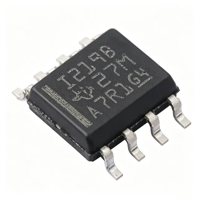
INA219BIDR - 26V 12-Bit I2C Power Monitor | Texas Instruments
MPN: INA219BIDR ✓ Active| Qty | Unit Price | Extended |
|---|---|---|
| 1 | $2.85 | $2.85 |
| 10 | $2.56 | $25.60 |
| 100 | $2.1 | $210.00 |
| 500 | $1.75 | $875.00 |
| 1,000 | $1.42 | $1,420.00 |
Drop-in alternatives for INA219BIDR — same package, pin-to-pin compatible. Different-package parts requiring PCB rework are excluded.
Quick Comparison Tool — Select alternative parts for side-by-side comparison:
INA219AIDR
✅ Drop-In✓ In Stock
$0.4136 / Unit
View Datasheet →INA219BID
✅ Drop-In📋 Reference alternative (not in catalog)
INA219AIDCNR
✅ Drop-In✓ In Stock
$1.12 / Unit
View Datasheet →INA219BIDR Maximum Ratings & Electrical Characteristics
| Function | High-side bidirectional current shunt and power monitor |
| Bus Voltage Range | 0 V to 26 V |
| Supply Voltage | 3.0 V to 5.5 V |
| ADC Resolution | 12 bit |
| Accuracy | 0.5% (maximum) over temperature (INA219B grade) |
| Interface | I2C / SMBUS compatible |
| Programmable Addresses | 16 |
| Measured Parameters | Current, voltage, power |
| Calibration | Programmable calibration register |
| Filtering | Programmable conversion times and filtering options |
| Architecture | Zero-drift, bidirectional |
| Operating Temperature | -40C to +125C |
| Package | SOIC-8 |
| Mounting Type | Surface Mount |
| Category | PMIC - Current Regulation/Management |
| RoHS Status | [DATA_NEEDED: RoHS status] |
INA219BIDR Pin Configuration
| Pin 1 | IN+ — Shunt voltage positive sense input (high side) |
| Pin 2 | IN- — Shunt voltage negative sense input |
| Pin 3 | GND — Ground reference |
| Pin 4 | VS — Power supply, 3.0 V to 5.5 V |
| Pin 5 | SDA — I2C/SMBUS data |
| Pin 6 | SCL — I2C/SMBUS clock |
| Pin 7 | ALERT — Alert output for overcurrent/undervoltage conditions |
| Pin 8 | A0 — I2C address select |
Safe Operating Area (SOA) & Thermal Characteristics
No official SOA curve available for this digital IC. Always operate within absolute maximum ratings specified in the datasheet. Ensure adequate cooling and derate as needed.
Typical Applications
INA219BIDR is suitable for 6 applications: Server Power Management, Battery Charger Monitoring, Telecom Equipment Power Supervision, Test and Measurement Instruments, Industrial Automation Power Monitoring, Embedded and IoT Device Power Budgeting.
Server Power Management
The INA219BIDR monitors rail current and power on server boards, reporting through I2C to a BMC or baseboard controller. Its 0.5% maximum accuracy over temperature supports precise power budgeting and thermal management, while the 26 V bus range covers common intermediate rails. The internal multiplier computes power directly, cutting host polling overhead, and 16 programmable addresses let a single controller monitor many rails across the system.
Recommended
Battery Charger Monitoring
The bidirectional zero-drift architecture of the INA219BIDR measures both charge and discharge current through one high-side shunt, ideal for battery chargers. With 0.5% accuracy from -40C to +125C, coulomb-style current tracking stays reliable across temperature. The ALERT pin flags overcurrent conditions, and the programmable calibration register lets designers set full-scale current range to match the chosen shunt resistor precisely.
Recommended
Telecom Equipment Power Supervision
Telecom racks run 12 V and 24 V distribution rails within the INA219BIDR's 0-26 V bus range, making it a natural high-side supervisor. High-side sensing keeps the ground path undisturbed across shared-ground shelves. Programmable conversion times and filtering reject noise from switching loads, and the SMBUS-compatible interface integrates with standard shelf-management controllers for remote current, voltage, and power reporting.
Recommended
Test and Measurement Instruments
Bench instruments and automated test equipment use the INA219BIDR to log device-under-test current draw with 12-bit resolution. The zero-drift input stage removes offset drift that would corrupt long-duration soak tests, and programmable filtering enables stable readings across changing loads. The calibration register supports automated full-scale reconfiguration when switching between DUT classes without redesigning the sense circuit.
Recommended
Industrial Automation Power Monitoring
PLC I/O modules and motor-control cabinets benefit from the INA219BIDR's -40C to +125C rating and 26 V bus capability for tracking actuator and driver supply current. The 0.5% accuracy over temperature supports predictive-maintenance analytics that detect motor stall or degraded wiring via current signatures. Multiple devices on one I2C bus with 16 addresses allow centralized monitoring across distributed modules.
Recommended
Embedded and IoT Device Power Budgeting
Battery-powered IoT nodes use the INA219BIDR to characterize and continuously monitor current consumption, verifying sleep-current targets in the microamp range thanks to the 10 uV/LSB-class shunt resolution of the 12-bit ADC. Compact SOIC-8 fits space-limited boards, and the low processor burden of direct power readouts suits always-on monitoring. The ALERT pin wakes the host on overcurrent events without continuous polling.
Recommended
Recommended Products Summary
Engineering reference data for INA219BIDR — comparison, design guidance, and compliance information.
Selection Guide
Comparison with Alternatives
| Parameter | This Product | INA219AIDR | INA219BID | INA226AIDR |
|---|---|---|---|---|
| Package | SOIC-8 | SOIC-8 - same | SOIC-8 - same | VSSOP-10 - different |
| Brand | Texas Instruments | Texas Instruments | Texas Instruments | Texas Instruments |
| ADC Resolution | 12 bit | 12 bit | 12 bit | 16 bit |
| Bus Voltage Range | 0 V to 26 V | 0 V to 26 V | 0 V to 26 V | 0 V to 36 V |
| Max Accuracy | 0.5% over temperature (B grade) | A-grade accuracy limits [DATA_NEEDED] | 0.5% over temperature | 0.1% [DATA_NEEDED] |
| Supply Voltage | 3.0 V to 5.5 V | 3.0 V to 5.5 V | 3.0 V to 5.5 V | 2.7 V to 5.5 V |
| Interface | I2C / SMBUS | I2C / SMBUS | I2C / SMBUS | I2C / SMBUS |
| Programmable Addresses | 16 | 16 | 16 | 16 |
Key Differentiators
- B-grade 0.5% maximum accuracy over temperature (vs INA219AIDR)
- On-chip power computation reduces host overhead (vs INA226AIDR)
- Bidirectional high-side sensing (vs MAX471 (Maxim/ADI))
Design Notes
Route the IN+ and IN- shunt sense traces as a Kelvin connection directly at the shunt resistor pads. Any trace resistance in series with the sense lines adds measurement error proportional to its ratio to the shunt value. Keep the sense pair short and symmetrical, and do not share sense points with high-current load paths.
Decouple the VS pin (pin 4) with a 0.1 uF ceramic capacitor placed as close to the pin as possible. The supply range is 3.0 V to 5.5 V; ensure the rail never dips below 3.0 V during brownout or the calibration register contents may become invalid after reset. Re-initialize calibration after every power cycle in software.
Verify bus voltage stays within 0-26 V absolute ratings including transients; 24 V industrial rails with inductive loads can exceed this. The calibration register must be written after each power-up before current readings are valid - raw shunt readings are valid but amperes/power registers are not until calibrated. Use the ALERT pin rather than polling for fault conditions in battery systems.
Compliance Information
Compliance status not stated in verified search snippets; confirm on TI product page Quality & Environmental data before production.




