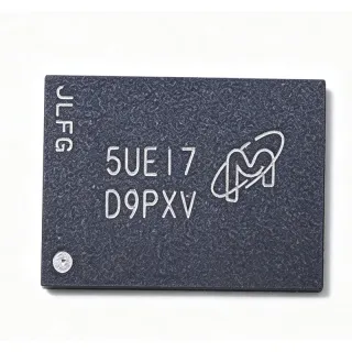
MT25QL128ABB1EW7-CAUT - 128Mb SPI NOR Flash 133MHz | Micron
MPN: MT25QL128ABB1EW7-CAUT ✓ Active| Qty | Unit Price | Extended |
|---|---|---|
| 1 | $3.2 | $3.20 |
| 10 | $2.85 | $28.50 |
| 100 | $2.4 | $240.00 |
| 500 | $2.05 | $1,025.00 |
| 1,000 | $1.8 | $1,800.00 |
Drop-in alternatives for MT25QL128ABB1EW7-CAUT — same package, pin-to-pin compatible. Different-package parts requiring PCB rework are excluded.
Quick Comparison Tool — Select alternative parts for side-by-side comparison:
MT25QL128ABB1EW7-CSIT
✅ Drop-In📋 Reference alternative (not in catalog)
MT25QL128ABA1EW7-0SIT
✅ Drop-In📋 Reference alternative (not in catalog)
MT25QL256ABB1EW7-CAUT
✅ Drop-In ⚠️ 参数待验证📋 Reference alternative (not in catalog)
MT25QL512ABB1EW7-CAUT
✅ Drop-In ⚠️ 参数待验证📋 Reference alternative (not in catalog)
MT25QL064ABB1EW7-CAUT
✅ Drop-In ⚠️ 参数待验证📋 Reference alternative (not in catalog)
MT25QL128ABB1EW7-CAUT Maximum Ratings & Electrical Characteristics
| Memory Type | FLASH - NOR Memory IC |
| Density | 128 Mbit (16 MB) |
| Interface | SPI - Quad I/O |
| Maximum Clock Frequency | 133 MHz |
| Supply Voltage | 2.7 V to 3.6 V (3 V class) |
| Operating Temperature | -40C to +125C |
| Process Technology | 45 nm IT |
| Package | 8-WPDFN (6x5 mm) (MLP8) |
| Mounting Type | Surface Mount |
| FBGA / Marking Code | RW314 |
| Sector Size | 64 KB (with 4 KB subsector erase) |
| Read Modes | SPI, Dual I/O, Quad I/O, XIP |
| Automotive Qualification | Automotive grade (-CAUT suffix) |
| Product Longevity Program | No |
| Programming Voltage | 3 V (single supply, W#/VPP pin) |
MT25QL128ABB1EW7-CAUT Pin Configuration
| Pin 1 | S# — Chip select (active low) |
| Pin 2 | DQ1 — Serial data output / DQ1 in dual and quad I/O modes |
| Pin 3 | W# — Write protect (active low) / VPP programming voltage input |
| Pin 4 | VSS — Ground |
| Pin 5 | DQ0 — Serial data input / DQ0 in dual and quad I/O modes |
| Pin 6 | C — Serial clock input |
| Pin 7 | DQ3 — HOLD# in SPI mode / DQ3 in quad I/O mode |
| Pin 8 | VCC — Power supply (2.7 V to 3.6 V) |
Safe Operating Area (SOA) & Thermal Characteristics
No official SOA curve available for this digital IC. Always operate within absolute maximum ratings specified in the datasheet. Ensure adequate cooling and derate as needed.
Typical Applications
MT25QL128ABB1EW7-CAUT is suitable for 6 applications: Automotive ECU Boot Flash, Industrial PLC and Motor Drives, Networking and Communication Equipment, Embedded Linux / RTOS Boot Devices, Automotive Instrument Cluster and Infotainment, Battery-Powered and Portable Devices.
Automotive ECU Boot Flash
The MT25QL128ABB1EW7-CAUT is purpose-built for automotive ECU boot code storage, with its -40C to +125C automotive temperature range and AEC-grade qualification path aligning with under-hood and body-control environments. In a typical engine, gearbox, or body-domain controller, the MCU or SoC fetches its boot code and calibration firmware over the quad I/O SPI bus at 133 MHz, using XIP mode for low-latency direct execution. The 64 KB sector architecture supports 4 KB subsector erase, allowing calibration data to be updated without erasing the boot image. Placed close to the MCU with short SPI traces, the 8-WPDFN (6x5) footprint occupies minimal board area. Its single 3 V supply simplifies the power tree compared with dual-voltage parallel NOR solutions.
Recommended
Industrial PLC and Motor Drives
Industrial programmable logic controllers, servo drives, and motor inverters demand firmware storage that survives wide temperature swings, vibration, and frequent parameter updates. The MT25QL128ABB1EW7-CAUT's 128 Mb capacity holds bootloader, RTOS image, and application code, while its -40C to +125C operation covers control-cabinet and drive-integrated environments. Quad I/O at 133 MHz reduces boot time significantly versus single-bit SPI, and XIP mode allows the main controller to execute directly from flash during early startup. The 4 KB subsector erase granularity lets drive parameters and fault logs be updated in the field without long erase cycles affecting the firmware region. Hardware write protection on the W#/VPP pin guards the boot image against accidental corruption during commissioning.
Recommended
Networking and Communication Equipment
Routers, switches, and baseband modules use serial NOR flash to store bootloader, OS loader, and configuration images. The MT25QL128ABB1EW7-CAUT's 133 MHz quad I/O interface delivers the throughput needed to load multi-megabyte firmware quickly during power-on, minimizing perceived boot latency. The 16 MB capacity accommodates redundant (A/B) firmware slots for fail-safe over-the-air or web-based upgrades, with the 64 KB sector map simplifying image layout and management. The 8-WPDFN (6x5 mm) package fits dense line-card and SFP-module-adjacent layouts where board real estate is scarce. Micron's XIP support allows early CPU bring-up directly from flash, and deep power-down mode reduces standby draw in always-on but low-duty-cycle equipment.
Recommended
Embedded Linux / RTOS Boot Devices
Embedded Linux and RTOS platforms (ARM Cortex-A/M, RISC-V) typically store SPL, U-Boot, device tree, and kernel images in SPI NOR flash. The MT25QL128ABB1EW7-CAUT provides 16 MB - enough for a compact kernel plus recovery loader - and its quad I/O 133 MHz reads shorten kernel decompression and boot time measurably versus 50 MHz single-bit flash. Micron's XIP mode supports SPL execution directly from the SPI bus, and the standard MT25Q command set is supported by mainline U-Boot and Linux MTD SPI-NOR drivers, reducing integration effort. The 4 KB subsector erase permits frequent update of U-Boot environment variables without disturbing the kernel partition, improving field-upgrade reliability in connected IoT gateways and edge devices.
Recommended
Automotive Instrument Cluster and Infotainment
Digital instrument clusters and infotainment head units require fast, reliable boot storage for GPU firmware, bootloader chains, and configuration data. The MT25QL128ABB1EW7-CAUT's automotive -40C to +125C rating and qualification pedigree match cockpit electronics requirements, while its 133 MHz quad I/O interface accelerates early boot so displays and safety tell-tales appear within mandated timing windows. The 16 MB capacity stores boot, calibration, and graphics microcode, with hardware write protection isolating safety-relevant boot blocks from updateable user content. Placed beside the SoC on the same power domain (2.7-3.6 V), it avoids level-shifting complexity. The exposed-pad MLP8 package provides solid solder-joint reliability under automotive thermal cycling profiles.
Recommended
Battery-Powered and Portable Devices
Portable, wearable, and battery-backed instruments benefit from the MT25QL128ABB1EW7-CAUT's deep power-down mode and 3 V single-supply operation, which fit typical Li-ion rail power trees without extra regulators. In these designs, the flash stores bootloader, application firmware, and sensor calibration tables; quad I/O at 133 MHz lets the MCU finish boot and return to low-power sleep states quickly, preserving battery budget. The compact 8-WPDFN 6x5 mm footprint suits space-constrained handheld and wearable PCBs, and the industrial-capable temperature range plus automotive grade options provide margin for devices exposed to sunlight or vehicle cabins. Its standard SPI command interface connects directly to virtually any MCU with a hardware SPI or QSPI peripheral, minimizing glue logic.
Recommended
Recommended Products Summary
Engineering reference data for MT25QL128ABB1EW7-CAUT — comparison, design guidance, and compliance information.
Selection Guide
Comparison with Alternatives
| Parameter | This Product | MT25QL128ABB1EW7-CSIT | MT25QL128ABA1EW7-0SIT | MT25QL256ABB1EW7-CAUT | MT25QL512ABB1EW7-CAUT | MT25QL064ABB1EW7-CAUT |
|---|---|---|---|---|---|---|
| Package | 8-WPDFN (6x5 mm) (MLP8) | 8-WPDFN (6x5 mm) - same | 8-WPDFN (6x5 mm) - same | 8-WPDFN (6x5 mm) - same | 8-WPDFN (6x5 mm) - same | 8-WPDFN (6x5 mm) - same |
| Brand | Micron Technology | Micron Technology | Micron Technology | Micron Technology | Micron Technology | Micron Technology |
| Density | 128 Mbit (16 MB) | 128 Mbit (16 MB) | 128 Mbit (16 MB) | 256 Mbit (32 MB) | 512 Mbit (64 MB) | 64 Mbit (8 MB) |
| Max Clock Frequency | 133 MHz | 133 MHz | 133 MHz | 133 MHz | 133 MHz | 133 MHz |
| Interface | SPI / Dual I/O / Quad I/O | SPI / Dual I/O / Quad I/O | SPI / Dual I/O / Quad I/O | SPI / Dual I/O / Quad I/O | SPI / Dual I/O / Quad I/O | SPI / Dual I/O / Quad I/O |
| Operating Temperature | -40C to +125C (automotive) | -40C to +85C (industrial) | -40C to +85C (industrial) | -40C to +125C (automotive) | -40C to +125C (automotive) | -40C to +125C (automotive) |
| Addressing | 3-byte (4-byte optional) | 3-byte (4-byte optional) | 3-byte (4-byte optional) | 3-byte (4-byte optional) | 4-byte required above 128 Mb boundary | 3-byte |
| Target Market | Automotive (AEC-grade path) | Industrial | Industrial | Automotive | Automotive | Automotive |
Key Differentiators
- Automotive temperature qualification (vs MT25QL128ABB1EW7-CSIT)
- Lower second-source risk than cross-brand swaps (vs MT25QL128ABA1EW7-0SIT)
- Right-sized 128 Mb density in 8-pin footprint (vs MT25QL512ABB1EW7-CAUT)
Design Notes
At 133 MHz quad I/O, SPI trace lengths become a real constraint. Keep S#, C, and DQ0-DQ3 traces under 10 cm where possible, match clock-to-data skew within the datasheet setup/hold budget, and avoid routing the SPI bus across power-plane splits. Add 22-33 ohm series resistors on C and DQ lines if ringing appears at the receiver. In quad mode, DQ3 doubles as HOLD#/output-enable, so it must be actively driven by the host in quad reads - do not pull it to a fixed rail, or read throughput collapses.
QUAD mode is not enabled by default: set the appropriate bit in the enhanced volatile (or non-volatile) configuration register during initialization, or issue the quad-peripheral-interface entry command per your bootloader. Forgetting this step makes the device run in single-bit SPI at reduced throughput. Also note W#/VPP is a dual-function pin - if used as hardware write protect, ensure it is not asserted during programming of protected regions. Confirm 4-byte vs 3-byte addressing expectations if migrating from or to 512 Mb variants.
Use the exposed pad under the 8-WPDFN (6x5) package as the primary ground connection and solder it to a Via-in-pad or short thermal-tie ground plane for reliable grounding and mechanical strength under automotive vibration profiles. Follow the IPC-recommended MLP8 land pattern in the Micron package drawing, and place a 100 nF ceramic decoupling capacitor within 3 mm of pin 8 (VCC) plus a 10 uF bulk capacitor nearby. Inspect solder joints with X-ray or AOI since the pad-side joints are hidden beneath the package.
Compliance Information
Automotive grade (-CAUT suffix) with -40C to +125C operation per Micron part catalog. RoHS/REACH/lead-free status not stated in the provided web data - confirm on Micron's official part detail page.