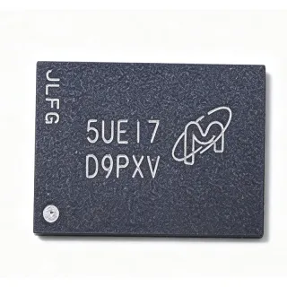
N25Q064A13ESEA0F - 64Mb SPI NOR Flash 108MHz | Micron
MPN: N25Q064A13ESEA0F ✓ Active| Qty | Unit Price | Extended |
|---|---|---|
| 1 | $0 | $0.00 |
| 10 | $0 | $0.00 |
| 100 | $0 | $0.00 |
| 500 | $0 | $0.00 |
| 1,000 | $0 | $0.00 |
Drop-in alternatives for N25Q064A13ESEA0F — same package, pin-to-pin compatible. Different-package parts requiring PCB rework are excluded.
Quick Comparison Tool — Select alternative parts for side-by-side comparison:
N25Q064A13E12A0F
✅ Drop-In✓ In Stock
$2.85 / Unit
View Datasheet →N25Q064A11ESEA0F
✅ Drop-In✓ In Stock
$1.19 / Unit
View Datasheet →N25Q064A13EF8A0E
✅ Drop-In✓ In Stock
$3.2 / Unit
View Datasheet →N25Q064A13EW74ME
✅ Drop-In📋 Reference alternative (not in catalog)
N25Q032A13EF4A0F
✅ Drop-In✓ In Stock
$1.25 / Unit
View Datasheet →N25Q064A13ESEA0F Maximum Ratings & Electrical Characteristics
| Memory Type | NOR Flash - Serial SPI |
| Memory Size | 64 Mbit (8 MB) |
| Interface | SPI (1-bit / 2-bit / 4-bit) |
| Max Clock Frequency | 108 MHz |
| Supply Voltage | 3 V (2.7 V to 3.6 V class) |
| Organization | 64M x1 / 32M x2 / 16M x4 |
| Access Time | 7 ns |
| Package | 8-SO Wide (SOP-8 W) |
| Mounting Type | Surface Mount |
| XIP Mode | Supported (execute-in-place) |
| Program / Erase Suspend | Supported |
| Hardware / Software Reset | Supported |
| Packaging | Tape & Reel (TR variant) |
| Lifecycle Status | Active |
N25Q064A13ESEA0F Pin Configuration
| Pin 1 | S# — Chip select (active low) |
| Pin 2 | DQ1 — Serial data output (SO) |
| Pin 3 | W#/VPP — Write protect / deep power-down voltage input |
| Pin 4 | GND — Ground |
| Pin 5 | DQ0 — Serial data input (SI) |
| Pin 6 | C — Serial clock (SCK) |
| Pin 7 | HOLD#/DQ3 — Hold / quad data line 3 |
| Pin 8 | VCC — Power supply (3V) |
Safe Operating Area (SOA) & Thermal Characteristics
No official SOA curve available for this digital IC. Always operate within absolute maximum ratings specified in the datasheet. Ensure adequate cooling and derate as needed.
Typical Applications
N25Q064A13ESEA0F is suitable for 6 applications: Firmware Boot Storage, Industrial Controllers, Computing Modules, Embedded Data Logging, Networking Equipment, Firmware Boot in Consumer Electronics.
Firmware Boot Storage
The N25Q064A13ESEA0F serves as boot code storage for MCU and SoC platforms that fetch firmware from SPI NOR at reset. Its 108 MHz quad-SPI clock and 64 Mb density accommodate 8 MB images with headroom for second-stage loaders, while XIP mode lets the processor execute directly from flash, cutting boot time and RAM overhead. The 7 ns access figure reflects fast internal read latency for sequential code fetch. Designers should confirm the boot ROM supports the N25Q command set and XIP confirmation bits, and follow the datasheet power-up requirements to guarantee the flash is ready when the host samples its first instruction vector.
Recommended
Industrial Controllers
Programmable logic controllers, motor drives, and factory automation nodes store firmware, parameter tables, and event logs in serial NOR flash. The N25Q064A13ESEA0F fits this role with its 3V supply, 64 Mb capacity, and program/erase suspend that lets logging writes pause code execution without stalling control loops. The power loss rescue sequence and AC reset specifications protect data when industrial power dips occur. In these environments the wide 8-SO package also simplifies hand assembly for service and repair. Engineers should budget erase cycles across wear-leveled sectors and verify the extended operating temperature grade decoded in the ordering code matches the enclosure thermal profile.
Recommended
Computing Modules
COM Express, SOM, and embedded computing modules carry a serial NOR flash for BIOS/UEFI firmware and platform settings. The N25Q064A13ESEA0F provides 8 MB, which is a common BIOS image size, and its quad I/O at 108 MHz supports fast BIOS shadowing on POST. XIP support and hardware/software reset behavior ease integration with x86 and ARM southbridge/boot controllers. The 8-pin wide SOIC keeps the footprint small on dense carrier boards. Designers should verify BIOS vendor support for the N25Q command set and ensure VCC decoupling meets the datasheet power-up and power-down requirements to avoid corrupt firmware during hot insertion or brownout.
Recommended
Embedded Data Logging
Data loggers for energy meters, medical devices, and environmental monitoring append records to non-volatile storage over long lifetimes. The N25Q064A13ESEA0F offers 64 Mb of sector- and block-erasable NOR storage with page programming and erase suspend/resume, allowing a logger to continue reporting while flash management runs in the background. NOR bit-reliability suits small-record integrity better than NAND, and the 3V rail matches battery-backed systems. Plan wear leveling across the 8 MB array to spread program/erase cycles, and use the software reset command to recover the bus if the host firmware watchdog resets mid-transaction.
Recommended
Networking Equipment
Routers, switches, and access points store boot code, device trees, and configuration in SPI NOR flash. The N25Q064A13ESEA0F's 8 MB holds dual firmware images for fail-safe A/B upgrades in many designs, and 108 MHz quad reads shorten boot and image verification time. The XIP confirmation-bit mechanism and reset specifications integrate cleanly with network SoC boot ROMs. Because networking hardware runs continuously, the program/erase suspend feature lets configuration writes occur without interrupting packet processing reads from the same device. Verify the SoC's QSPI controller timing at 108 MHz and use short, impedance-controlled clock traces for signal integrity.
Recommended
Firmware Boot in Consumer Electronics
Smart home devices, set-top boxes, and appliance controllers use low-cost SPI NOR for their primary firmware. The N25Q064A13ESEA0F combines the 8-pin wide SOIC footprint that consumer assemblies already support with Micron's proven N25Q command set, reducing qualification effort. Its 3V operation aligns with typical 3.3 V logic rails, and the 64 Mb capacity covers growing OTA-verified image sizes. In battery-adjacent products, confirm the standby/depth-power-down current figures from the full datasheet against the product's sleep budget. For high-volume consumer builds, the TR tape-and-reel variant feeds pick-and-place lines directly.
Recommended
Recommended Products Summary
Engineering reference data for N25Q064A13ESEA0F — comparison, design guidance, and compliance information.
Selection Guide
Comparison with Alternatives
| Parameter | This Product | N25Q064A13E12A0F | N25Q064A11ESEA0F | N25Q032A13EF4A0F |
|---|---|---|---|---|
| Package | 8-SO W (SOP-8 W) | 8-SO W (SOP-8 W) - same | 8-SO W (SOP-8 W) - same | 8-SO W (SOP-8 W) - same |
| Brand | Micron Technology | Micron Technology | Micron Technology | Micron Technology |
| Density | 64 Mbit | 64 Mbit | 64 Mbit | 32 Mbit |
| Max Clock | 108 MHz | [DATA_NEEDED] | [DATA_NEEDED] | [DATA_NEEDED] |
| Supply Voltage Class | 3 V | 3 V | 3 V (grade 11 decode) | 3 V |
| I/O Width | 1 / 2 / 4 bit | 1 / 2 / 4 bit | 1 / 2 / 4 bit | 1 / 2 / 4 bit |
| XIP Support | Yes | Yes | Yes | Yes |
| Lifecycle Status | Active | [DATA_NEEDED] | [DATA_NEEDED] | [DATA_NEEDED] |
Key Differentiators
- Full 64 Mb density at 108 MHz quad-SPI (vs N25Q032A13EF4A0F)
- Wide SOIC for serviceability (vs N25Q064A13EF8A0E)
- XIP plus program/erase suspend (vs N25Q064A11ESEA0F)
Design Notes
Follow the N25Q datasheet power-up and power-down requirements: VCC must rise monotonically and the device should not be accessed until VCC stabilizes above the minimum supply. Place a 100 nF ceramic decoupling capacitor within 2 mm of the VCC pin plus a 4.7 uF bulk capacitor per supply rail group. The datasheet's power loss rescue sequence must be implemented in host firmware so an interrupted erase/program is recovered at next boot.
At 108 MHz, treat the SPI bus as a transmission line concern: keep clock traces under 100 mm, route clock away from data lines, and add series termination (22-33 ohm) on the clock if ringing appears. For quad mode, HOLD#/DQ3 transitions carry data, so equalize trace lengths among DQ0-DQ3. Ensure the QSPI controller mode (mode 0 or 3) matches the command protocol and verify timing at temperature corners.
Do not toggle W#/VPP during program or erase operations - it can abort or corrupt the operation. Entering and terminating XIP requires specific confirmation bits per the datasheet; a controller reset alone does not guarantee XIP exit, so implement the documented termination sequence. Also verify the grade decode of the exact ordering code (SE vs E12 vs F8 suffixes) before substituting family members in production.
Compliance Information
Compliance certificates for this exact ordering code should be downloaded from the Micron part-detail page; the provided web data did not state RoHS/REACH status explicitly.