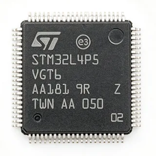
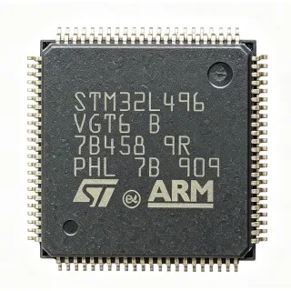
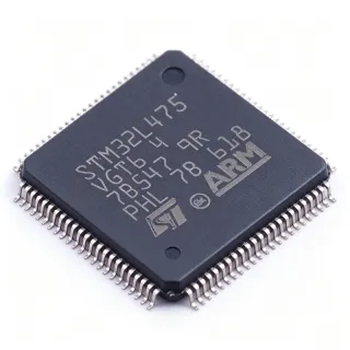
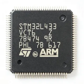
STM32L486VGT6 - ARM Cortex-M4F MCU 1MB Flash | STMicroelectronics
MPN: STM32L486VGT6 ✓ Active| Qty | Unit Price | Extended |
|---|---|---|
| 1 | $12.67 | $12.67 |
| 10 | $11.4 | $114.00 |
| 100 | $10.13 | $1,013.00 |
| 500 | $9.12 | $4,560.00 |
| 1,000 | $8.11 | $8,110.00 |
Drop-in alternatives for STM32L486VGT6 — same package, pin-to-pin compatible. Different-package parts requiring PCB rework are excluded.
Quick Comparison Tool — Select alternative parts for side-by-side comparison:
STM32L486VGT6TR
✅ Drop-In📋 Reference alternative (not in catalog)
STM32L486VGT7
✅ Drop-In📋 Reference alternative (not in catalog)
STM32L476VGT6
✅ Drop-In✓ In Stock
$4.09 / Unit
View Datasheet →STM32L496VGT6
✅ Drop-In✓ In Stock
$9.5455 / Unit
View Datasheet →GD32F450VGT6
⚡ Same Package📋 Reference alternative (not in catalog)
STM32L486VGT6 Maximum Ratings & Electrical Characteristics
| Core | ARM Cortex-M4F |
| Maximum Frequency | 80 MHz |
| Flash Memory | 1 MB |
| SRAM | 128 KB |
| Package | 100-LQFP (14x14 mm) |
| Supply Voltage Range | 1.71 V to 3.6 V |
| DMIPS | 100 |
| ADC | 12-bit, 5 MSPS |
| DAC | 2x 12-bit |
| Communication Interfaces | USART, SPI, I2C, USB OTG FS, CAN, SAI |
| Cryptographic Acceleration | AES, DES, Hash |
| True Random Number Generator | Yes |
| Low-Power Modes | Sleep, Low-power Run, Low-power Sleep, Stop 2, Standby, Shutdown |
| Shutdown Current | 100 nA |
| Operating Temperature | -40C to +85C |
| RoHS Status | Compliant |
STM32L486VGT6 Pin Configuration
| Pin 1 | PE2 — GPIO / TRACECLK |
| Pin 2 | PE3 — GPIO / TRACED0 |
| Pin 3 | PE4 — GPIO / TRACED1 |
| Pin 4 | PE5 — GPIO / TRACED2 |
| Pin 5 | PE6 — GPIO / TRACED3 |
| Pin 6 | VBAT — Battery backup supply |
| Pin 7 | PC13 — GPIO / RTC_TAMP1 |
| Pin 8 | PC14 — GPIO / OSC32_IN |
| Pin 9 | PC15 — GPIO / OSC32_OUT |
| Pin 10 | PF0 — GPIO / OSC_IN |
| Pin 11 | PF1 — GPIO / OSC_OUT |
| Pin 12 | NRST — Reset |
| Pin 13 | PC0 — GPIO / ADC_IN10 |
| Pin 14 | PC1 — GPIO / ADC_IN11 |
| Pin 15 | PC2 — GPIO / ADC_IN12 |
| Pin 16 | PC3 — GPIO / ADC_IN13 |
| Pin 17 | VDD — Digital power supply |
| Pin 18 | VSS — Ground |
| Pin 19 | PC4 — GPIO / ADC_IN14 |
| Pin 20 | PC5 — GPIO / ADC_IN15 |
| Pin 21 | PB0 — GPIO / ADC_IN8 |
| Pin 22 | PB1 — GPIO / ADC_IN9 |
| Pin 23 | PB2 — GPIO / BOOT1 |
| Pin 24 | PB10 — GPIO / I2C2_SCL |
| Pin 25 | PB11 — GPIO / I2C2_SDA |
| Pin 26 | VDD — Digital power supply |
| Pin 27 | VSS — Ground |
| Pin 28 | PB12 — GPIO / SPI2_NSS |
| Pin 29 | PB13 — GPIO / SPI2_SCK |
| Pin 30 | PB14 — GPIO / SPI2_MISO |
| Pin 31 | PB15 — GPIO / SPI2_MOSI |
| Pin 32 | PC6 — GPIO / I2S2_MCK |
| Pin 33 | PC7 — GPIO / I2S2_SCK |
| Pin 34 | PC8 — GPIO / I2S2_SD |
| Pin 35 | PC9 — GPIO / I2S2_WS |
| Pin 36 | PA0 — GPIO / ADC_IN0 / WKUP1 |
| Pin 37 | PA1 — GPIO / ADC_IN1 |
| Pin 38 | PA2 — GPIO / ADC_IN2 / USART2_TX |
| Pin 39 | PA3 — GPIO / ADC_IN3 / USART2_RX |
| Pin 40 | VDD — Digital power supply |
| Pin 41 | VSS — Ground |
| Pin 42 | PA4 — GPIO / ADC_IN4 / DAC_OUT1 |
| Pin 43 | PA5 — GPIO / ADC_IN5 / DAC_OUT2 |
| Pin 44 | PA6 — GPIO / ADC_IN6 |
| Pin 45 | PA7 — GPIO / ADC_IN7 |
| Pin 46 | PC10 — GPIO / USART3_TX |
| Pin 47 | PC11 — GPIO / USART3_RX |
| Pin 48 | PC12 — GPIO / USART3_CK |
| Pin 49 | PD0 — GPIO / FSMC_D2 |
| Pin 50 | PD1 — GPIO / FSMC_D3 |
| Pin 51 | PD2 — GPIO / FSMC_D4 |
| Pin 52 | PD3 — GPIO / FSMC_D5 |
| Pin 53 | PD4 — GPIO / FSMC_D6 |
| Pin 54 | PD5 — GPIO / FSMC_D7 |
| Pin 55 | PD6 — GPIO / FSMC_D8 |
| Pin 56 | PD7 — GPIO / FSMC_D9 |
| Pin 57 | VDD — Digital power supply |
| Pin 58 | VSS — Ground |
| Pin 59 | PD8 — GPIO / FSMC_D10 |
| Pin 60 | PD9 — GPIO / FSMC_D11 |
| Pin 61 | PD10 — GPIO / FSMC_D12 |
| Pin 62 | PD11 — GPIO / FSMC_D13 |
| Pin 63 | PD12 — GPIO / FSMC_D14 |
| Pin 64 | PD13 — GPIO / FSMC_D15 |
| Pin 65 | PD14 — GPIO / FSMC_D0 |
| Pin 66 | PD15 — GPIO / FSMC_D1 |
| Pin 67 | PE0 — GPIO / FSMC_NBL0 |
| Pin 68 | PE1 — GPIO / FSMC_NBL1 |
| Pin 69 | PE7 — GPIO / FSMC_D4 |
| Pin 70 | PE8 — GPIO / FSMC_D5 |
| Pin 71 | PE9 — GPIO / FSMC_D6 |
| Pin 72 | PE10 — GPIO / FSMC_D7 |
| Pin 73 | PE11 — GPIO / FSMC_D8 |
| Pin 74 | PE12 — GPIO / FSMC_D9 |
| Pin 75 | PE13 — GPIO / FSMC_D10 |
| Pin 76 | PE14 — GPIO / FSMC_D11 |
| Pin 77 | PE15 — GPIO / FSMC_D12 |
| Pin 78 | VDD — Digital power supply |
| Pin 79 | VSS — Ground |
| Pin 80 | PB3 — GPIO / SPI1_SCK |
| Pin 81 | PB4 — GPIO / SPI1_MISO |
| Pin 82 | PB5 — GPIO / SPI1_MOSI |
| Pin 83 | PB6 — GPIO / I2C1_SCL |
| Pin 84 | PB7 — GPIO / I2C1_SDA |
| Pin 85 | BOOT0 — Boot mode selection |
| Pin 86 | PB8 — GPIO / I2C1_SCL |
| Pin 87 | PB9 — GPIO / I2C1_SDA |
| Pin 88 | PA8 — GPIO / USB_OTG_FS_SOF |
| Pin 89 | PA9 — GPIO / USB_OTG_FS_VBUS |
| Pin 90 | PA10 — GPIO / USB_OTG_FS_ID |
| Pin 91 | PA11 — GPIO / USB_OTG_FS_DM |
| Pin 92 | PA12 — GPIO / USB_OTG_FS_DP |
| Pin 93 | PA13 — GPIO / SWDIO |
| Pin 94 | PA14 — GPIO / SWCLK |
| Pin 95 | PA15 — GPIO / JTDI |
| Pin 96 | PC0 — GPIO / ADC_IN10 |
| Pin 97 | PC1 — GPIO / ADC_IN11 |
| Pin 98 | PC2 — GPIO / ADC_IN12 |
| Pin 99 | PC3 — GPIO / ADC_IN13 |
| Pin 100 | VDD — Digital power supply |
Safe Operating Area (SOA) & Thermal Characteristics
No official SOA curve available for this digital IC. Always operate within absolute maximum ratings specified in the datasheet. Ensure adequate cooling and derate as needed.
Typical Applications
STM32L486VGT6 is suitable for 6 applications: Industrial Sensors, Smart Meters, Medical Devices, Wearable Electronics, IoT Nodes, Audio Processing.
Industrial Sensors
The STM32L486VGT6 is ideal for industrial sensors due to its ultra-low-power modes (100 nA shutdown) and high-performance Cortex-M4F core. It can process sensor data with DSP instructions and communicate via CAN or SAI interfaces. The 12-bit ADC at 5 MSPS enables high-speed data acquisition, while the cryptographic acceleration ensures secure data transmission. In a typical industrial sensor node, the MCU reads analog sensor values, processes them with the FPU, and transmits results over CAN bus, maintaining low average power consumption for battery-powered operation.
Recommended
Smart Meters
The STM32L486VGT6 excels in smart meter applications by combining metrology calculations with communication protocols and display control. Its 80 MHz Cortex-M4F core with FPU handles complex energy calculation algorithms, while the LCD driver and touch sensing controller manage the user interface. The ultra-low-power modes enable long battery life, and the cryptographic acceleration secures data for remote reading. In a smart electricity meter, the MCU samples voltage and current via the ADC, computes energy consumption, and communicates via PLC or RF modules, all while maintaining low power consumption.
Recommended
Medical Devices
The STM32L486VGT6 is well-suited for portable medical devices like glucose monitors and pulse oximeters. Its ultra-low-power operation (100 nA shutdown) extends battery life, while the FPU and DSP instructions handle signal processing for biosignal analysis. The cryptographic acceleration ensures patient data security. In a wearable health monitor, the MCU reads sensor data, processes ECG or SpO2 signals, and communicates via BLE, all while maintaining a compact form factor and long battery life.
Recommended
Wearable Electronics
The STM32L486VGT6 is perfect for wearable devices due to its small 100-LQFP package and ultra-low-power modes. The Cortex-M4F core with FPU enables efficient sensor fusion algorithms for motion tracking, while the touch sensing controller handles user input. The device's 1 MB Flash provides ample storage for firmware and data logging. In a smartwatch, the MCU manages the display, sensors, and wireless communication, achieving weeks of battery life through aggressive power management.
Recommended
IoT Nodes
The STM32L486VGT6 is an excellent choice for IoT nodes, offering a balance of performance and power efficiency. Its multiple communication interfaces (USB OTG FS, CAN, SAI) support various connectivity options, while the cryptographic acceleration ensures secure data transmission. The ultra-low-power modes enable battery-powered operation for years. In a typical IoT sensor node, the MCU collects data from sensors, processes it locally, and transmits it via LoRa or NB-IoT, all while maintaining minimal power consumption.
Recommended
Audio Processing
The STM32L486VGT6's Cortex-M4F core with FPU and DSP instructions makes it suitable for audio processing applications. The SAI interface supports I2S audio data, and the 12-bit DAC can output analog audio. The device's low power consumption is ideal for portable audio devices. In a voice-controlled device, the MCU captures audio via the ADC, performs noise reduction and keyword detection using the FPU, and communicates results via USB or wireless interfaces.
Recommended
Recommended Products Summary
Engineering reference data for STM32L486VGT6 — comparison, design guidance, and compliance information.
Selection Guide
Comparison with Alternatives
| Parameter | This Product | STM32L486VGT6TR | STM32L486VGT7 | STM32L476VGT6 | STM32L496VGT6 | GD32F450VGT6 |
|---|---|---|---|---|---|---|
| Package | 100-LQFP (14x14) | 100-LQFP (14x14) - same | 100-LQFP (14x14) - same | 100-LQFP (14x14) - same | 100-LQFP (14x14) - same | 100-LQFP (14x14) - same |
| Brand | STMicroelectronics | STMicroelectronics | STMicroelectronics | STMicroelectronics | STMicroelectronics | GigaDevice |
| Core | ARM Cortex-M4F | ARM Cortex-M4F | ARM Cortex-M4F | ARM Cortex-M4F | ARM Cortex-M4F | ARM Cortex-M4F |
| Maximum Frequency | 80 MHz | 80 MHz | 80 MHz | 80 MHz | 80 MHz | 200 MHz |
| Flash Memory | 1 MB | 1 MB | 1 MB | 1 MB | 1 MB | 1 MB |
| SRAM | 128 KB | 128 KB | 128 KB | 128 KB | 320 KB | 256 KB |
| Cryptographic Acceleration | Yes (AES, DES, Hash) | Yes (AES, DES, Hash) | Yes (AES, DES, Hash) | No | Yes (AES, DES, Hash) | No |
| Supply Voltage Range | 1.71V to 3.6V | 1.71V to 3.6V | 1.71V to 3.6V | 1.71V to 3.6V | 1.71V to 3.6V | 2.6V to 3.6V |
Key Differentiators
- Integrated cryptographic acceleration (vs STM32L476VGT6)
- True random number generator (TRNG) (vs STM32L476VGT6)
- Ultra-low-power shutdown mode (vs GD32F450VGT6)
Design Notes
For ultra-low-power operation, configure unused GPIOs as analog inputs to avoid leakage currents. Use the low-power modes (Stop 2, Standby, Shutdown) to minimize power consumption. The shutdown mode consumes only 100 nA, making it ideal for battery-powered devices. Ensure the power supply is stable and decoupled with 100 nF capacitors close to each VDD pin and a 4.7 uF capacitor at the main supply.
Place decoupling capacitors (100 nF) as close as possible to each VDD pin, and a 4.7 uF bulk capacitor at the main supply. For the crystal oscillator, place the crystal and load capacitors close to the OSC_IN/OSC_OUT pins to minimize parasitic capacitance. Use a ground plane to reduce noise and improve EMC performance.
Ensure the BOOT0 pin is properly configured to select the correct boot mode. For SWD programming, connect PA13 (SWDIO) and PA14 (SWCLK) with pull-up/pull-down resistors as recommended in the datasheet. Avoid driving the VBAT pin with more than 3.6V to prevent damage to the backup domain.
Compliance Information
RoHS compliant per STMicroelectronics product page. Not AEC-Q100 qualified - this is a general-purpose MCU.