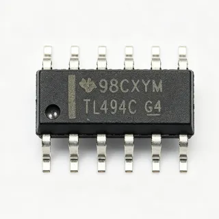
TPS54331DR - 3A 28V Buck Converter 570kHz | Texas Instruments
MPN: TPS54331DR ✓ Active| Qty | Unit Price | Extended |
|---|---|---|
| 1 | $1.85 | $1.85 |
| 10 | $1.66 | $16.60 |
| 100 | $1.32 | $132.00 |
| 500 | $1.1 | $550.00 |
| 1,000 | $0.85 | $850.00 |
TPS54331DR Overview
A buck converter, or step-down converter, is a DC-DC switching regulator that efficiently reduces a higher input voltage to a lower output voltage. Unlike linear regulators, buck converters use switching elements and an external inductor to transfer energy, achieving high efficiency especially at large input-to-output voltage differences. The TPS54331DR is a non-synchronous buck converter within the broader power management IC family, using an external diode for low-side rectification, which simplifies design and reduces cost compared to synchronous converters.
Key features include a fixed 570kHz switching frequency, current mode control with internal slope compensation, and Eco-mode pulse-skipping that improves light-load efficiency. The device offers 1uA shutdown supply current for battery-powered applications, adjustable soft-start, cycle-by-cycle overcurrent protection, and thermal shutdown. The integrated high-side MOSFET minimizes conduction losses.
Architecturally, current mode control compares the COMP pin voltage to the switch current each cycle to turn off the high-side MOSFET. This provides excellent line and load transient response and simplifies external compensation. Eco-mode automatically reduces switching frequency at light loads, maintaining efficiency across wide load ranges.
Typical applications include industrial power supplies, set-top boxes, LCD displays, distributed power systems, and consumer electronics. Its wide input range and 3A output make it ideal for powering FPGAs, DSPs, and microcontrollers from 12V or 24V buses, with output set precisely via external resistors.
Design tip: ensure proper input/output capacitor selection and a tight PCB layout to minimize parasitic inductance. The COMP pin requires an external RC network for loop compensation, and the bootstrap capacitor must sit close to the BOOT pin for reliable high-side gate drive.
Drop-in alternatives for TPS54331DR — same package, pin-to-pin compatible. Different-package parts requiring PCB rework are excluded.
Variants in this series
Same-series models that are drop-in compatible with TPS54331DR (same form factor and footprint) — differing in Output Voltage Range, Input Voltage Range, Package, Switching Frequency, Topology.
Quick Comparison Tool — Select alternative parts for side-by-side comparison:
TPS54331DDAR
⚡ Same Package📋 Reference alternative (not in catalog)
TPS54202DDCR
⚡ Same Package✓ In Stock
$0.12 / Unit
View Datasheet →TPS5430DDAR
⚡ Same Package✓ In Stock
$1.19 / Unit
View Datasheet →TPS5450DDARQ1
⚡ Same Package📋 Reference alternative (not in catalog)
TPS54360DDAR
⚡ Same Package✓ In Stock
$0.95 / Unit
View Datasheet →TPS54331DR Maximum Ratings & Electrical Characteristics
| Topology | Non-synchronous Buck (Step-Down) |
| Input Voltage Range | 3.5 V to 28 V |
| Output Voltage Range | 0.8 V to 25 V (adjustable) |
| Maximum Output Current | 3 A |
| Switching Frequency | 570 kHz (fixed) |
| Control Method | Current mode with internal slope compensation |
| Light Load Feature | Eco-mode pulse skipping |
| Shutdown Supply Current | 1 uA |
| High-Side MOSFET | Integrated, low RDS(on) |
| Soft-Start | Adjustable via SS/TR pin |
| Protection Features | Overcurrent (cycle-by-cycle), thermal shutdown |
| Operating Temperature | -40C to +125C (ambient); -40C to +150C (TJ) |
| Package | 8-SOIC (0.154 in, 3.90 mm width), D |
| Mounting Type | Surface Mount |
| Number of Outputs | 1 |
| RoHS Status | Compliant |
TPS54331DR Pin Configuration
| Pin 1 | BOOT — Bootstrap capacitor connection for high-side gate drive |
| Pin 2 | VIN — Input supply voltage, 3.5V to 28V |
| Pin 3 | EN — Enable input (active high) |
| Pin 4 | SS/TR — Soft-start / tracking, set with external capacitor |
| Pin 5 | VSENSE — Feedback input from output voltage divider |
| Pin 6 | COMP — Loop compensation, external RC network |
| Pin 7 | GND — Ground |
| Pin 8 | PH — Phase / switch node to inductor and catch diode |
Typical Applications
TPS54331DR is suitable for 6 applications: Industrial 24V Bus Power Supply, FPGA and DSP Point-of-Load Power, Set-Top Box and Consumer Electronics, LCD Display Backlight and Panel Power, Distributed Power Intermediate Bus Conversion, Battery-Powered Portable Equipment.
Industrial 24V Bus Power Supply
The TPS54331DR's 28V input rating directly tolerates 24V industrial rails with margin, delivering up to 3A at outputs from 0.8V to 25V. In PLC I/O modules and sensor conditioning boards, it steps 24V down to 5V or 3.3V logic supplies at 570kHz, allowing a compact 10-22uH inductor. Cycle-by-cycle overcurrent and thermal shutdown protect against shorted loads and hot cabinets, while Eco-mode maintains efficiency during standby.
Recommended
FPGA and DSP Point-of-Load Power
FPGA and DSP core rails draw fast load steps; the TPS54331DR's current mode control gives single-cycle transient response, keeping 1V-1.2V core rails within tolerance when processors wake from idle. Its 3A capacity covers mid-range devices, and 570kHz operation keeps the output filter small. Place the converter near the processor with low-ESR ceramic output capacitance to minimize droop during current steps.
Recommended
Set-Top Box and Consumer Electronics
Consumer set-top boxes need efficient standby and low cost. The TPS54331DR's Eco-mode pulse skipping raises light-load efficiency, cutting standby power, while the non-synchronous topology avoids the higher cost of synchronous converters. Its 1uA shutdown current supports compliance with low standby power limits, and the standard SOIC-8 keeps assembly cost low on high-volume consumer boards.
Recommended
LCD Display Backlight and Panel Power
LCD monitors and displays combine 5V logic, 12V or 3.3V panel supplies, and backlight driver inputs. The TPS54331DR converts a 12V-24V adapter input into these rails at up to 3A, and its adjustable soft-start limits inrush that could trip the adapter's protection. Fixed 570kHz switching stays above the AM band, easing EMI filter design for display products.
Recommended
Distributed Power Intermediate Bus Conversion
In distributed power architectures, a 24V intermediate bus feeds local point-of-load converters. The TPS54331DR serves as a mid-level converter stepping 24V to 5V or 12V distribution rails at 3A per card. Its wide 3.5V-28V input tolerates bus transients per typical industrial specs, while adjustable soft-start allows sequencing multiple converters on one board to control inrush during hot-swap or power-up.
Recommended
Battery-Powered Portable Equipment
Portable instruments powered by 4S-6S battery packs benefit from the TPS54331DR's 1uA shutdown current and 3.5V low-end input that works down to nearly discharged 4S lithium packs. Eco-mode pulse skipping keeps light-load efficiency high when the system idles, extending runtime. Its 3A capability also supports burst loads from radios or displays without output collapse.
Recommended
Recommended Products Summary
Engineering reference data for TPS54331DR — comparison, design guidance, and compliance information.
Selection Guide
Comparison with Alternatives
| Parameter | This Product | TPS54331DDAR | TPS54202DDCR | TPS5450QDDARQ1 | TPS54360DDAR |
|---|---|---|---|---|---|
| Package | 8-SOIC (D) | SO-8 PowerPAD (DDA) | SO-8 PowerPAD (DDC) | SO-8 PowerPAD (DDA) | SO-8 PowerPAD (DDA) |
| Brand | Texas Instruments | Texas Instruments | Texas Instruments | Texas Instruments | Texas Instruments |
| Input Voltage Range | 3.5V to 28V | 3.5V to 28V | 4.5V to 28V | 5.5V to 36V | 4.5V to 60V |
| Output Current | 3 A | 3 A | 2 A | 5 A | 3.5 A |
| Switching Frequency | 570 kHz (fixed) | 570 kHz (fixed) | 480 kHz | 500 kHz (fixed) | Adjustable |
| Topology | Non-synchronous buck | Non-synchronous buck | Synchronous buck | Non-synchronous buck | Non-synchronous buck |
| Automotive Grade | No | No | No | Yes (AEC-Q100) | No |
| PCB Footprint Compatibility | Standard SOIC-8 | SOIC-8 pinout + PowerPAD land pattern | Different land pattern (SOT-23-8 style DDC) | SOIC-8 pinout + PowerPAD land pattern | SOIC-8 PowerPAD land pattern, different pin functions |
Key Differentiators
- 3.5V low-end input allows deep battery discharge operation (vs TPS5450QDDARQ1)
- Standard SOIC-8 footprint without exposed pad (vs TPS54331DDAR)
- Eco-mode pulse skipping for standby efficiency (vs LM2596SX-ADJ/NOPB)
Design Notes
Keep the PH, VIN, and GND loop as small as possible: place the input capacitor, catch diode, and inductor within a few millimeters of the IC. Use a solid ground plane under the converter. Place the BOOT capacitor (0.1uF) directly adjacent to BOOT and PH pins. Route the VSENSE feedback trace away from the PH node to avoid switching-noise coupling into the feedback loop.
Select the catch diode for reverse voltage above VIN(max) plus switch-node ringing (Schottky such as a 40V B340A for 24V inputs) and average current rating above output current. Inductor should be rated 20-30% above the 3A peak with saturation current margin; typical values 10-22uH at 570kHz per the TI datasheet formulas. Verify RMS ripple current in the input capacitor.
The standard SOIC-8 (D) package has higher thermal resistance than the PowerPAD variant. Estimate dissipation from high-side MOSFET conduction plus switching losses; at 24V input, 5V/3A output, expect roughly 1.5-2.5W. Provide at least 1 square inch of copper pour on the GND pins or move to the TPS54331DDAR (PowerPAD) if ambient exceeds 70C.
Do not omit the COMP compensation network - values depend on output capacitance and load range per datasheet equations. Ensure EN pin is not left floating above abs-max if tied to VIN through a divider. The SS/TR capacitor sets soft-start; too small a value can cause output overshoot on start-up. Output voltage above 25V or input above 28V violates datasheet limits.
Compliance Information
RoHS compliant and lead-free per TI product page. Non-automotive grade; use TPS5450QDDARQ1 for AEC-Q100 requirements.