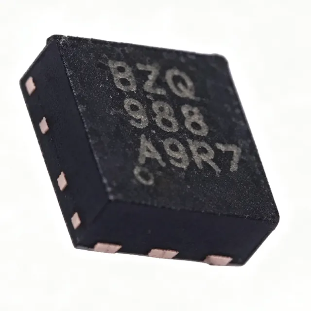
TPS61160DRVR - Boost White LED Driver 18V | Texas Instruments
MPN: TPS61160DRVR ✓ Active| Qty | Unit Price | Extended |
|---|---|---|
| 1 | $0.28 | $0.28 |
| 10 | $0.25 | $2.50 |
| 100 | $0.21 | $21.00 |
| 500 | $0.18 | $90.00 |
| 1,000 | $0.16 | $160.00 |
Drop-in alternatives for TPS61160DRVR — same package, pin-to-pin compatible. Different-package parts requiring PCB rework are excluded.
Quick Comparison Tool — Select alternative parts for side-by-side comparison:
TPS61165DRVR
✅ Drop-In📋 Reference alternative (not in catalog)
TPS61161DRVR
✅ Drop-In📋 Reference alternative (not in catalog)
TPS61160ADRVRG4
✅ Drop-In📋 Reference alternative (not in catalog)
TPS61291DRVR
✅ Drop-In📋 Reference alternative (not in catalog)
TPS61160DRVR Maximum Ratings & Electrical Characteristics
| Topology | Inductive Step-Up (Boost) LED Driver |
| Input Voltage Range | 2.7 V to 18 V |
| Internal Switch FET Rating | 40 V |
| Switch Current Limit | 700 mA |
| Switching Frequency | 600 kHz (fixed) |
| Maximum Duty Cycle | 93% |
| LED String Length | Up to 10 LEDs in series |
| Open LED Protection | 26 V |
| Feedback Reference | 200 mV |
| Dimming | Direct PWM and single-wire digital (PWM on CTRL) |
| Number of Outputs | 1 |
| Operating Temperature | -40C to +85C |
| Package | 6-WSON (DRV), 2 mm x 2 mm with thermal pad |
| Mounting Type | Surface Mount |
| Packaging | Tape & Reel (R suffix) |
| Application | LCD backlighting, constant-current LED lighting |
TPS61160DRVR 6-wson (drv), 2 mm x 2 mm with thermal pad Pin Configuration Guide
Complete pinout information for TPS61160DRVR (6-wson (drv), 2 mm x 2 mm with thermal pad package). This power device features gate, drain, and source terminals. For non-polarized packages, refer to the manufacturer datasheet for exact pin 1 orientation and footprint details. Common applications include power supply design, motor driving, and load switching.

No detailed pinout data available for TPS61160DRVR.
Refer to the datasheet for full pin configuration.
Safe Operating Area (SOA) & Thermal Characteristics
No official SOA curve available for this component. Always operate within absolute maximum ratings specified in the datasheet. Ensure adequate cooling and derate as needed.
Typical Applications
TPS61160DRVR is suitable for 6 applications: Smartphone LCD Backlighting, Tablet and PND Display Backlight, Battery-Powered LED Lighting, Automotive Cluster and Infotainment Backlight (Non-Q1), Portable Instrument and HMI Indicator Lighting, USB-Powered Accent and Decorative Lighting.
Smartphone LCD Backlighting
The TPS61160DRVR fits smartphone LCD backlighting because its 2-mm x 2-mm WSON package conserves board area and its 600 kHz switching frequency permits a small, low-profile inductor suited to thin form factors. In a typical circuit, the boost converter drives a series LED string from a single-cell Li-ion battery (2.7 V to 4.2 V), regulating string current through a 200 mV sense resistor for uniform brightness. The single-wire digital dimming on the CTRL pin lets the baseband processor control brightness without a dedicated PWM peripheral, while stepless analog dimming eliminates visible flicker at low backlight levels that degrade user experience in dark environments.
Recommended
Tablet and PND Display Backlight
Tablets and portable navigation devices need brighter backlights with longer LED strings than phones, and the TPS61160DRVR addresses this with up to 10 series LEDs, a 93% maximum duty cycle, and an internal 40-V switch FET that supports the required step-up ratio from a 5 V USB input or Li-ion pack. The 26 V open-LED protection safely limits output if the string opens, protecting the thin-film panel wiring. Its 700 mA switch limit covers mid-size panel current needs, and the 200 mV feedback reference keeps sense-resistor dissipation below a few milliwatts, preserving battery runtime in always-on navigation use cases.
Recommended
Battery-Powered LED Lighting
For general constant-current LED illumination powered by multi-cell alkaline or NiMH stacks, the TPS61160DRVR accepts inputs from 2.7 V to 18 V, spanning three to twelve alkaline cells. The boost topology maintains constant LED current as the battery discharges and its voltage sags, preventing the dimming drift typical of resistor-ballasted designs. The 600 kHz fixed frequency keeps switching losses manageable at the 700 mA peak switch current, and direct PWM dimming allows user brightness control with a simple pushbutton interface. Low shutdown current preserves battery life between uses, making it suitable for flashlights, lanterns, and indicator luminaires.
Recommended
Automotive Cluster and Infotainment Backlight (Non-Q1)
In 12 V automotive-style display rails, the TPS61160DRVR operates directly from nominal 12 V supplies within its 18 V maximum input, boosting to drive series LED strings for small instrument or infotainment backlights. The 40-V internal switch FET provides ample flyback voltage margin over the 26 V open-LED clamp, reducing the risk of switch overstress during load transients. Designers should note this standard-grade part is rated -40C to +85C; for AEC-Q100-qualified illumination designs, pair or substitute with qualified drivers such as the LP8860-Q1 or TPS92691QPWPTQ1 depending on string power and channel count requirements.
Recommended
Portable Instrument and HMI Indicator Lighting
Handheld meters, medical monitors, and industrial HMIs use small LED strings for keypad and status backlighting, and the TPS61160DRVR suits these duty cycles with its low component count: one inductor, one sense resistor, and small ceramic capacitors around the 6-pin WSON package. The 200 mV feedback reference permits accurate current setting with standard 1% resistors, and the single-wire interface accepts a logic-level PWM from any MCU, easing brightness calibration in production. The -40C to +85C operating range covers typical indoor industrial and portable medical environments without derating the 700 mA switch limit.
Recommended
USB-Powered Accent and Decorative Lighting
USB ports supply a regulated 5 V rail, comfortably inside the 2.7 V to 18 V input range of the TPS61160DRVR, making it a natural fit for accent strips, display cases, and decorative luminaires drawing a few hundred milliamps. The boost converter steps 5 V up to the series string voltage while the internal FET removes the cost and layout area of an external switch. The 600 kHz frequency keeps inductance requirements low (small shielded chip inductors suffice at 700 mA peak current), and PWM dimming enables simple color-mixing or mood-lighting control from a USB microcontroller or dedicated lighting MCU.
Recommended
Recommended Products Summary
Engineering reference data for TPS61160DRVR — comparison, design guidance, and compliance information.
Selection Guide
Comparison with Alternatives
| Parameter | This Product | TPS61165DRVR | TPS61161DRVR | TPS61160ADRVRG4 | TPS61291DRVR |
|---|---|---|---|---|---|
| Package | 6-WSON (DRV) 2x2 mm | 6-WSON (DRV) 2x2 mm - same | 6-WSON (DRV) 2x2 mm - same | 6-WSON (DRV) 2x2 mm - same | 6-WSON (DRV) 2x2 mm - same |
| Brand | Texas Instruments | Texas Instruments | Texas Instruments | Texas Instruments | Texas Instruments |
| Input Voltage Range | 2.7 V to 18 V | 2.7 V to 18 V | 2.7 V to 18 V | 2.7 V to 18 V | [DATA_NEEDED] |
| Switch Current Limit | 700 mA | Higher than 700 mA | 700 mA | 700 mA | [DATA_NEEDED] |
| Open LED Protection | 26 V | [DATA_NEEDED] | 38 V | 26 V | N/A (general-purpose boost) |
| Switching Frequency | 600 kHz | 600 kHz | 600 kHz | 600 kHz | [DATA_NEEDED] |
| LED String / Output Role | Up to 10 series LEDs, current regulated | LED driver, longer/brighter strings | Up to 10+ series LEDs (38 V clamp) | Up to 10 series LEDs | General-purpose voltage boost |
| Dimming Interface | PWM + single-wire digital on CTRL | PWM + single-wire digital | PWM + single-wire digital | PWM + single-wire digital | None (enable only) |
| Lifecycle Status | Active | Active | Active | Active | Active |
Key Differentiators
- Lowest-cost family member for strings within 26 V (vs TPS61161DRVR)
- Upgrade path without redesign (vs TPS61165DRVR)
- Integrated 40-V switch FET reduces BOM (vs TPS61291DRVR)
Design Notes
Verify the worst-case LED string voltage against the 26 V open-LED protection clamp of the TPS61160. White LED forward voltage rises as current is set and temperature falls, so a nominal 8-LED string can approach the clamp in cold conditions, causing false open-LED faults and LED flashing. Compute Vstring(max) from the datasheet LED VF(max) at minimum temperature and target current, and keep it at least 2-3 V below 26 V, or switch to the pin-compatible TPS61161DRVR with its 38 V clamp.
Keep the power loop - input capacitor, inductor, internal SW FET, and output capacitor - as tight as possible on the 2x2-mm WSON footprint. Connect the exposed thermal pad directly to a ground pour with an array of vias; the pad is the main thermal and electrical ground path for the DRV package. Place the current-sense resistor close to the FB pin with short, direct traces to avoid noise pickup at the 200 mV reference level, and route the CTRL trace away from the SW node to prevent dimming glitches at the 600 kHz switching edges.
Size the sense resistor using the 200 mV feedback reference: R_sense = 0.2 V / I_LED(target). For example, 20 mA LED current needs about 10 ohm. Estimated dissipation is only 4 mW at 20 mA, which is why the low reference improves efficiency versus 1 V+ reference competitors. Ensure the input supply can deliver the peak switch current (700 mA limit at 600 kHz); weak sources or thin input traces will cause input droop, reduced duty cycle, and inability to reach the full 10-LED string voltage.
Compliance Information
RoHS compliant and lead-free per distributor categorization of this standard TI device. REACH, halogen-free, and conflict-minerals declarations should be confirmed from official TI environmental documentation for the exact orderable part number.







