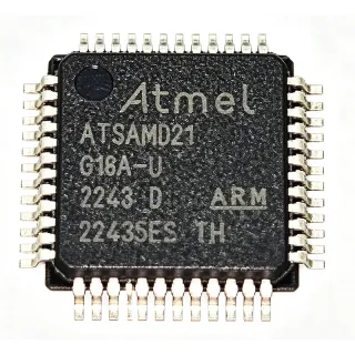
ATMEGA1609-AU - 8-bit AVR MCU, 20MHz, 16KB Flash | Microchip
MPN: ATMEGA1609-AU ✓ Active| Qty | Unit Price | Extended |
|---|---|---|
| 1 | $1.95 | $1.95 |
| 10 | $1.76 | $17.60 |
| 100 | $1.52 | $152.00 |
| 500 | $1.32 | $660.00 |
| 1,000 | $1.15 | $1,150.00 |
ATMEGA1609-AU Overview
An 8-bit AVR microcontroller is a Harvard-architecture RISC processor that executes most instructions in a single clock cycle, placing it in the broader hierarchy of microcontrollers (MCU) under embedded processors and system-on-chip devices. The megaAVR 0-series is Microchip's general-purpose AVR family, combining a hardware multiplier, Core Independent Peripherals (CIPs), and event system for deterministic, interrupt-free operation.
Key features include the 20 MHz AVR CPU with hardware multiplier, Core Independent Peripherals such as configurable custom logic (CCL), a 12-bit ADC, comparators, and timer/counter types A and B. The event system routes peripheral signals without CPU intervention, cutting latency and code size. Multi-voltage operation from 1.8V to 5.5V allows use in both battery-powered and 5V industrial designs.
The ATmega1609 architecture is based on the AVR RISC core with a two-stage pipeline, executing an average of one instruction per cycle. Program Flash is self-programmable for bootloaders, and the 256-byte EEPROM retains calibration data through power cycles. Peripheral features such as the 16-bit Type A PWM timers and the CCL logic blocks offload real-time tasks from software.
Typical applications include industrial control and automation nodes, consumer appliances, and IoT sensor endpoints where 16 KB Flash and rich analog peripherals are sufficient. The Functional Safety (FuSa) documented variant family also suits safety-related designs.
Design consideration: at 5V the device tolerates the full 20 MHz clock, while at the 1.8V minimum supply the maximum frequency is derated per the datasheet frequency-versus-voltage curve; plan clock scaling with supply rails.
This page synthesizes verified distributor data, same-family drop-in alternatives, and design notes not found in the manufacturer datasheet, with pricing as of 2026-09-16.
Drop-in alternatives for ATMEGA1609-AU — same package, pin-to-pin compatible. Different-package parts requiring PCB rework are excluded.
Variants in this series
Same-series models that are drop-in compatible with ATMEGA1609-AU (same form factor and footprint) — differing in Core Processor, Connectivity, Peripherals, Package, Series.
Quick Comparison Tool — Select alternative parts for side-by-side comparison:
ATMEGA1609-AFR
✅ Drop-In✓ In Stock
$1.87 / Unit
View Datasheet →ATMEGA1608-AU
✅ Drop-In ⚠️ 参数待验证✓ In Stock
$0.86 / Unit
View Datasheet →ATMEGA3209-AU
✅ Drop-In ⚠️ 参数待验证✓ In Stock
$1.06 / Unit
View Datasheet →ATMEGA4809-AU
✅ Drop-In ⚠️ 参数待验证📋 Reference alternative (not in catalog)
ATMEGA809-AU
✅ Drop-In ⚠️ 参数待验证📋 Reference alternative (not in catalog)
ATMEGA1609-AU Maximum Ratings & Electrical Characteristics
| Core Processor | AVR 8-bit RISC |
| Core Size | 8-bit |
| Maximum Clock Frequency | 20 MHz |
| Flash Memory | 16 KB (16K x 8) |
| SRAM | 2 KB |
| EEPROM | 256 bytes |
| Operating Voltage Range | 1.8 V to 5.5 V |
| Connectivity | I2C, SPI, UART/USART |
| Series | megaAVR 0-series (ATmega808/809/1608/1609) |
| Package | 48-TQFP (7x7 mm) |
| Mounting Type | Surface Mount |
| Number of Pins | 48 |
| Hardware Multiplier | Yes |
| Peripherals | Brown-out Detect/Reset, POR, PWM, WDT, Core Independent Peripherals |
| Safety Qualification | Functional Safety (FuSa) supported family |
| Product Status | Active |
ATMEGA1609-AU 48-tqfp (7x7 mm) Pin Configuration Guide
Pin configuration for ATMEGA1609-AU (48-tqfp (7x7 mm) package). This digital IC includes GPIO, communication interfaces (UART, SPI, I2C), and power pins. Refer to the manufacturer datasheet for alternate pin functions and configuration options. Essential for embedded system design and PCB layout.

No detailed pinout data available for ATMEGA1609-AU.
Refer to the datasheet for full pin configuration.
Typical Applications
ATMEGA1609-AU is suitable for 6 applications: Industrial Control and Automation, IoT Sensor Endpoints, Consumer Appliances, Motor Control and Fan Drivers, Human Interface Devices and Lighting Control, Education, Prototyping and Hobby Electronics.
Industrial Control and Automation
The ATMEGA1609-AU fits industrial control nodes because it runs from a 5V rail with a full 20 MHz clock, integrates brown-out detection, power-on reset, and a watchdog timer, and exposes multiple UART/SPI/I2C interfaces for PLC I/O, motor control front-ends, and sensor hubs. Its Core Independent Peripherals and event system service time-critical tasks - PWM generation, quadrature decoding, and comparator tripping - without CPU intervention, improving determinism in polling-heavy designs. With 16 KB Flash and 2 KB SRAM, compact Modbus or CAN-adjacent slaves fit without external memory. The 48-pin TQFP provides up to 42 GPIO for relay driving, keypad scanning, and status LEDs, while the 1.8V to 5.5V range supports both legacy 5V panels and newer 3.3V subsystems on one board revision.
Recommended
IoT Sensor Endpoints
Battery- and line-powered IoT sensor nodes benefit from the ATMEGA1609-AU's combination of a 12-bit ADC, analog comparators, and low-power sleep modes across a 1.8V to 5.5V supply, letting one MCU span both primary-cell and regulated-supply designs. The event system routes ADC-ready and comparator outputs to timers without waking the CPU, dramatically reducing active time in duty-cycled sensing. I2C and SPI interfaces connect digital sensors (humidity, pressure, accelerometers), while a UART links to a radio module or RS-485 transceiver. The 256-byte EEPROM stores calibration coefficients and node addressing through power cycles. MegaCoreX Arduino support shortens prototyping, and the 16 KB/2 KB memory budget comfortably hosts a sensor stack with a lightweight protocol layer.
Recommended
Consumer Appliances
White goods, small kitchen appliances, and HVAC controllers use the ATMEGA1609-AU for its 5V noise immunity, integrated PWM Type A timers for heater and fan control, and brown-out protection that prevents EEPROM corruption during mains sags. The 42 available GPIO drive seven-segment displays, relays, and touch or mechanical button arrays, while the CCL configurable logic implements safety interlocks in hardware - for example, gating a heater PWM only when a door-switch comparator indicates closure. The 16 KB Flash accommodates state machines and display drivers, and the hardware multiplier accelerates PID loops for temperature regulation. Wide-voltage operation tolerates unregulated transformer-rectifier supplies common in appliance architectures, and the 48-pin TQFP simplifies assembly on two-layer boards.
Recommended
Motor Control and Fan Drivers
The ATMEGA1609-AU suits small BLDC and brushed-DC motor control through its Type A 16-bit PWM timers with complementary waveform outputs and dead-time insertion, plus analog comparators usable for over-current trip in hardware. The event system connects comparator outputs to timer fault inputs without software latency, protecting power stages during stalls. At 20 MHz with a hardware multiplier, field-oriented-control-adjacent scalar algorithms and commutation tables run with headroom in 16 KB Flash. I2C connects digital current sensors while a UART reports telemetry to a host controller. The 5V GPIO directly interfaces gate drivers and MOSFET pre-drivers, and the 1.8V to 5.5V range allows battery-powered tool designs to share firmware across cell-count variants.
Recommended
Human Interface Devices and Lighting Control
Keypanels, remote controls, and DMX or DALI-adjacent lighting controllers leverage the ATMEGA1609-AU's GPIO density, wake-on-pin-change sleep, and hardware PWM channels. The 48-pin TQFP exposes up to 42 I/O, enough for a 4x8 key matrix plus LED column drivers without external port expanders. Type B timers generate precise dimming waveforms while the ADC reads potentiometer or ambient-light inputs for adaptive brightness. The event system chains pin-change events to timers so button wake-up and debounce run with minimal firmware. At deep sleep currents typical of the megaAVR 0-series, battery-powered remotes achieve multi-year life; the 16 KB Flash holds lookup tables for color mixing and per-unit calibration stored in the 256-byte EEPROM during production.
Recommended
Education, Prototyping and Hobby Electronics
The ATMEGA1609-AU is an excellent teaching and prototyping MCU because MegaCoreX provides full Arduino IDE support for the megaAVR 0-series, and the same architecture powers the Arduino Uno WiFi Rev2 - so skills transfer directly. UPDI programming needs only a single pin plus ground, and a 1 kOhm resistor plus USB-UART adapter is sufficient with pyupdi, removing programmer cost barriers in classrooms. The Core Independent Peripherals (CCL, event system) offer hands-on learning of hardware-level design beyond software loops. DIP-adapter-friendly 7x7 mm TQFP and wide 1.8V to 5.5V operation make breadboard experiments forgiving. According to the MegaCoreX GitHub repository, all eight family members share tooling, so students can migrate from 8 KB to 48 KB devices seamlessly.
Recommended
Recommended Products Summary
Engineering reference data for ATMEGA1609-AU — comparison, design guidance, and compliance information.
Selection Guide
Comparison with Alternatives
| Parameter | This Product | ATMEGA1609-AFR | ATMEGA1608-AU | ATMEGA3209-AU | ATMEGA4809-AU | ATMEGA809-AU |
|---|---|---|---|---|---|---|
| Package | 48-TQFP (7x7 mm) | 48-TQFP (7x7 mm) - same | 48-TQFP (7x7 mm) - same | 48-TQFP (7x7 mm) - same | 48-TQFP (7x7 mm) - same | 48-TQFP (7x7 mm) - same |
| Brand | Microchip Technology | Microchip Technology | Microchip Technology | Microchip Technology | Microchip Technology | Microchip Technology |
| Flash Memory | 16 KB | 16 KB | 16 KB | 32 KB | 48 KB | 8 KB |
| SRAM | 2 KB | 2 KB | 2 KB | 4 KB | 6 KB | 1 KB |
| Max Clock Frequency | 20 MHz | 20 MHz | 20 MHz | 20 MHz | 20 MHz | 20 MHz |
| Supply Voltage | 1.8 V to 5.5 V | 1.8 V to 5.5 V | 1.8 V to 5.5 V | 1.8 V to 5.5 V | 1.8 V to 5.5 V | 1.8 V to 5.5 V |
| Connectivity | I2C, SPI, UART/USART | I2C, SPI, UART/USART | I2C, SPI, UART/USART | I2C, SPI, UART/USART | I2C, SPI, UART/USART | I2C, SPI, UART/USART |
| EEPROM | 256 bytes | 256 bytes | 256 bytes | 256 bytes | 256 bytes | 256 bytes |
Key Differentiators
- 16 KB Flash balance point of the megaAVR 0-series (vs ATMEGA809-AU)
- Cost-efficient versus 32/48 KB siblings (vs ATMEGA3209-AU)
- Same footprint packaging flexibility (vs ATMEGA1609-AFR)
Design Notes
The ATMEGA1609-AU accepts 1.8V to 5.5V, but maximum CPU frequency scales with supply: the full 20 MHz rating applies near the high end of the voltage range while low-voltage operation requires frequency derating per the frequency-versus-voltage curve in datasheet DS40002172. If your board runs from an LDO at 3.3V, verify the permitted clock before selecting a 20 MHz crystal or internal oscillator setting. Add 100 nF decoupling on each VDD pin pair and a 10 uF bulk capacitor; the two VDD pins (distributed around the 48-pin TQFP) must both be connected.
For the UPDI programming interface, reserve a 3-pin header (UPDI, GND, and optionally VDD) during PCB layout - retrofitting access to the single-wire UPDI pin after layout is the most common rework request for megaAVR 0-series boards. Keep the UPDI trace short and away from high-dV/dt nets such as relay or MOSFET gate drives, since UPDI is active from power-up. If in-field programming is planned, a series 1 kOhm resistor on UPDI allows the pin to double as a GPIO input in application mode.
Unlike classic AVRs, megaAVR 0-series parts have no dedicated RESET pin by default - reset is via the UPDI pin or brown-out, so legacy external-RC reset circuits are unnecessary and the pin saved can be used as GPIO. Also note that write access to configuration peripherals requires protected I/O sequences; direct register writes from application code to clock or reset controller registers will fault unless the CPU write-protection sequence is followed. Port EEPROM writes with interrupts disabled or use the built-in EEWRDY interrupt to avoid corruption during power loss.
Compliance Information
Standard commercial-grade Microchip MCU in TQFP with lead-free matte-tin finish (AU suffix). Verify REACH, halogen-free, and conflict-minerals declarations on the official Microchip product page compliance documents.