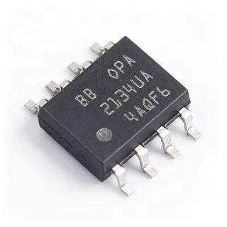
LM2904QDRQ1 - Dual 26V 700kHz Op Amp AEC-Q100 | TI
MPN: LM2904QDRQ1 ✓ Active| Qty | Unit Price | Extended |
|---|---|---|
| 1 | $0.32 | $0.32 |
| 10 | $0.29 | $2.90 |
| 100 | $0.26 | $26.00 |
| 500 | $0.24 | $120.00 |
| 1,000 | $0.22 | $220.00 |
| 3,000 | $0.2202 | $660.60 |
LM2904QDRQ1 Overview
An operational amplifier (op amp) is a high-gain differential-input voltage amplifier and a fundamental analog building block within the signal-chain hierarchy: op amp -> amplifier IC -> analog/mixed-signal IC -> semiconductor. A dual op amp integrates two independent amplifiers in one package, cutting board space and BOM cost for multi-channel signal conditioning.
Key features include a low 500 uA supply current per amplifier, a common-mode input range that includes ground (enabling true single-supply operation), internal frequency compensation, and output short-circuit protection. ESD protection exceeds 500 V per MIL-STD-883 Method 3015 and 200 V on the machine model, per the TI datasheet.
Technically, the bipolar process yields a typical 2 mV input offset voltage (7 mV max) and 20 nA typical input bias current. The 0.3 V/us slew rate and 700 kHz GBW suit low-frequency sensor and control loops; the output swings close to the negative rail but is not rail-to-rail. Operation remains stable with moderate capacitive loads.
Typical applications include automotive sensor signal conditioning (temperature, pressure, position), current sensing, active filters, DC motor control, and battery management front-ends, where the 26V rating allows direct operation from a 12V automotive battery rail with load-dump headroom.
Design tip: decouple VCC with a 0.1 uF ceramic close to pin 8, keep the input common-mode below VCC-1.5V, and buffer high-impedance sources to limit offset errors. For new automotive designs requiring 36V ratings and tighter offset, consider the next-generation LM2904B-Q1 family.
Drop-in alternatives for LM2904QDRQ1 — same package, pin-to-pin compatible. Different-package parts requiring PCB rework are excluded.
Variants in this series
Same-series models that are drop-in compatible with LM2904QDRQ1 (same form factor and footprint) — differing in Common-Mode Input Range, Input Offset Voltage, Package, Slew Rate.
Quick Comparison Tool — Select alternative parts for side-by-side comparison:
LM358QDRQ1
✓ In Stock
$0.18 / Unit
View Datasheet →LM2904BQDRQ1
📋 Reference alternative (not in catalog)
LM2904QDRG4Q1
📋 Reference alternative (not in catalog)
LM2904VQDR
📋 Reference alternative (not in catalog)
LM2904DR2G
📋 Reference alternative (not in catalog)
LM2904DT
📋 Reference alternative (not in catalog)
LM2904QDRQ1 Maximum Ratings & Electrical Characteristics
| Number of Channels | 2 |
| Supply Voltage Range (single) | 3 V to 26 V |
| Supply Voltage Range (dual) | ±1.5 V to ±13 V |
| Gain-Bandwidth Product | 700 kHz (typ) |
| Slew Rate | 0.3 V/us (typ) |
| Input Offset Voltage | 2 mV (typ), 7 mV (max) |
| Input Bias Current | 20 nA (typ) |
| Supply Current per Amplifier | 500 uA (typ) |
| Common-Mode Input Range | Includes ground (V-) |
| Output | Swings close to negative rail, not rail-to-rail |
| ESD Rating (HBM) | Exceeds 500 V (MIL-STD-883 Method 3015) |
| ESD Rating (MM) | 200 V |
| Automotive Qualification | AEC-Q100 qualified |
| Operating Temperature | -40C to +125C |
| Package | SOIC-8 (D) |
| Mounting Type | Surface Mount |
| Protection | Output short-circuit protection, internal frequency compensation |
LM2904QDRQ1 Pin Configuration
| Pin 1 | OUT A — Amplifier A output |
| Pin 2 | IN A- — Amplifier A inverting input |
| Pin 3 | IN A+ — Amplifier A non-inverting input |
| Pin 4 | V- / GND — Negative supply or ground (single supply) |
| Pin 5 | IN B+ — Amplifier B non-inverting input |
| Pin 6 | IN B- — Amplifier B inverting input |
| Pin 7 | OUT B — Amplifier B output |
| Pin 8 | V+ — Positive supply (3V to 26V) |
Typical Applications
LM2904QDRQ1 is suitable for 6 applications: Automotive Sensor Signal Conditioning, Low-Side Current Sensing, Active Filter Design, DC Motor Control Loops, Battery Management Front-Ends, Comparator and Level-Translation Functions.
Automotive Sensor Signal Conditioning
The LM2904QDRQ1 is AEC-Q100 qualified and rated -40C to +125C, directly matching automotive under-hood and body-zone temperature requirements. Its input common-mode range includes ground, so it amplifies sensor outputs near 0V from temperature, pressure, and position sensors on a single 12V rail. With a 700 kHz GBW, it handles low-bandwidth sensor loops easily. The 26V supply rating tolerates automotive battery transients, and the 500 uA per amplifier current keeps module quiescent draw low for always-on circuits.
Recommended
Low-Side Current Sensing
Because the LM2904QDRQ1 input common-mode range extends to ground, it is well suited to low-side current sensing across a shunt resistor on a 12V or 24V automotive rail. The amplifier gains the shunt voltage for an ADC or comparator. The 26V supply rating provides transient headroom, and output short-circuit protection guards against harness faults. Its 2 mV typical offset limits resolution on shunts below about 10 mV full-scale, so use a dedicated current-sense amplifier such as the INA2181 for microvolt-precision measurements.
Recommended
Active Filter Design
The internally compensated, unity-gain stable LM2904QDRQ1 implements Sallen-Key and multiple-feedback active filters for anti-aliasing and noise filtering. Its 700 kHz GBW supports corner frequencies into the tens of kilohertz with adequate Q, and the 0.3 V/us slew rate suits audio-band and control-loop filtering. Dual channels in one SOIC-8 package realize two filter poles per device, cutting board area and BOM count. The AEC-Q100 qualification allows these filters in automotive audio and sensor front-end paths.
Recommended
DC Motor Control Loops
The LM2904QDRQ1 conditions feedback signals in brushed DC motor control: it amplifies tachometer, back-EMF, or current-shunt feedback for MCU-based closed loops. The 26V rating tolerates battery transients, AEC-Q100 qualification fits vehicle body and pump modules, and the ground-sensing inputs read signals referenced to chassis ground. One amplifier can implement the error integrator while the second buffers the setpoint. Its 700 kHz GBW is ample for motor control loop bandwidths typically below 10 kHz, with stable operation under moderate capacitive loads.
Recommended
Battery Management Front-Ends
In 12V automotive and industrial battery systems, the LM2904QDRQ1 buffers cell-voltage and temperature inputs ahead of monitoring ADCs. Its 3V to 26V supply range operates directly from the battery rail, the 500 uA per amplifier draw minimizes drain in always-on supervision circuits, and the -40C to +125C range survives engine-bay placement. Use one channel as a unity-gain buffer for high-impedance dividers and the other as a comparator-stage driver. Note the 20 nA bias current adds divider error on very high impedance sources.
Recommended
Comparator and Level-Translation Functions
One LM2904QDRQ1 channel can run open-loop as a low-speed comparator for window detectors, threshold alarms, and fail-safe monitors in automotive modules. The ground-sensing inputs allow references near 0V, the 26V supply supports direct battery connection, and AEC-Q100 qualification meets vehicle reliability requirements. Because it is an op amp rather than a dedicated comparator, add hysteresis and expect microsecond-scale response; for fast trips use a purpose-built comparator such as the LM393DR in the same SOIC-8 pinout.
Recommended
Recommended Products Summary
Engineering reference data for LM2904QDRQ1 — comparison, design guidance, and compliance information.
Selection Guide
Comparison with Alternatives
| Parameter | This Product | LM2904BQDRQ1 | LM2904VQDR | LM2904DR2G | LM2904DT |
|---|---|---|---|---|---|
| Package | SOIC-8 (D) | SOIC-8 (D) - same | SOIC-8 (D) - same | SOIC-8 - same pinout | SOIC-8 - same pinout |
| Brand | Texas Instruments | Texas Instruments | Texas Instruments | onsemi | STMicroelectronics |
| Max Supply Voltage | 26 V | 32 V | 32 V | 26 V | 26 V |
| Gain-Bandwidth Product | 700 kHz (typ) | 700 kHz (typ) | 700 kHz (typ) | 700 kHz (typ) | 700 kHz (typ) |
| Slew Rate | 0.3 V/us | 0.3 V/us | 0.3 V/us | 0.3 V/us | 0.3 V/us |
| AEC-Q100 Qualification | Yes | Yes | No | Verify grade with onsemi | Verify grade with ST |
| Operating Temperature | -40C to +125C | -40C to +125C | -40C to +125C | -40C to +125C | -40C to +125C |
Key Differentiators
- Automotive AEC-Q100 qualification at commodity pricing (vs LM2904DR2G)
- Next-generation upgrade path (vs LM2904BQDRQ1)
- Ground-sensing single-supply input range (vs LM2904VQDR)
Design Notes
Decouple V+ (pin 8) with a 0.1 uF ceramic capacitor placed within 2-3 mm of the pin, plus a 1-10 uF bulk capacitor per rail. On single-supply automotive rails, add a series resistor and TVS diode ahead of the amplifier inputs if they can be exposed to transients beyond the 26V rating. Keep input traces short and guarded to limit leakage-induced offset errors with high-impedance sources.
Keep the input common-mode voltage below VCC-1.5V; exceeding it causes phase reversal-like behavior and output errors. The output is not rail-to-rail - it swings close to the negative rail but saturates roughly 1.5V below VCC, so design gain stages with output headroom. Do not rely on this op amp as a fast comparator; its response is in the microsecond range. For small shunt voltages, its 2 mV typical offset dominates accuracy.
With 500 uA per amplifier, self-heating is negligible in most designs, so the -40C to +125C AEC-Q100 rating is governed by ambient environment. In automotive engine-bay modules, verify that PCB substrate temperature including nearby power components stays below 125C junction, and prefer 2 oz copper or thermal vias near hot spot components on the same board.
Compliance Information
AEC-Q100 qualified per TI product page for the LM2904-Q1 family. RoHS/lead-free status per standard TI D package offering; verify REACH and halogen-free status on the TI product page.