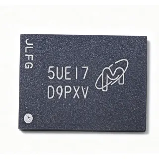
M25P10-AVMN3P/X - 1Mbit SPI NOR Flash 50MHz | Micron
MPN: M25P10-AVMN3P/X ✗ End of Life| Qty | Unit Price | Extended |
|---|---|---|
| 1 | $1.35 | $1.35 |
| 10 | $1.18 | $11.80 |
| 100 | $0.98 | $98.00 |
| 500 | $0.86 | $430.00 |
| 1,000 | $0.75 | $750.00 |
Drop-in alternatives for M25P10-AVMN3P/X — same package, pin-to-pin compatible. Different-package parts requiring PCB rework are excluded.
Quick Comparison Tool — Select alternative parts for side-by-side comparison:
M25P10-AVMN3P/Y
✅ Drop-In📋 Reference alternative (not in catalog)
M25P10-AVMN6P
✅ Drop-In📋 Reference alternative (not in catalog)
M25P10-AVMN3P
✅ Drop-In📋 Reference alternative (not in catalog)
M25P10-AVMN3P/X Maximum Ratings & Electrical Characteristics
| Memory Type | FLASH - NOR |
| Memory Size | 1 Mbit (128K x 8) |
| Interface | SPI Serial |
| Clock Frequency | 50 MHz |
| Supply Voltage | 2.3 V to 3.6 V |
| Page Program Time | 1.4 ms typical (up to 256 bytes) |
| Sector Erase Time | 0.65 s typical (256 Kbit) |
| Bulk Erase Time | 1.7 s typical (1 Mbit) |
| Write/Erase Cycles | 10000 |
| Operating Temperature | -40C to +125C (TA) |
| Package / Case | 8-SOIC (0.154 in, 3.90 mm width) |
| Mounting Type | Surface Mount (SMD/SMT) |
| Packaging | Tube |
| Write Protection | Hardware /W pin and software status register |
| Organization | 4 sectors x 256 Kbit, 256-byte pages |
| RoHS Status | unknown |
M25P10-AVMN3P/X Pin Configuration
| Pin 1 | /S — Chip select, active low |
| Pin 2 | Q — Serial data output (SPI DO) |
| Pin 3 | /W — Write protect input, active low |
| Pin 4 | VSS — Ground |
| Pin 5 | D — Serial data input (SPI DI) |
| Pin 6 | C — SPI clock input |
| Pin 7 | /HOLD — Hold input, pauses communication, active low |
| Pin 8 | VCC — Power supply, 2.3 V to 3.6 V |
Safe Operating Area (SOA) & Thermal Characteristics
No official SOA curve available for this digital IC. Always operate within absolute maximum ratings specified in the datasheet. Ensure adequate cooling and derate as needed.
Typical Applications
M25P10-AVMN3P/X is suitable for 6 applications: FPGA Configuration Storage, Microcontroller Boot Firmware, Industrial Data Logging, Set-Top Box and Networking Parameter Storage, Display and LCD Setting Storage, Battery-Powered Low-Voltage Embedded Systems.
FPGA Configuration Storage
The M25P10-AVMN3P/X stores FPGA bitstreams over its 50 MHz SPI interface, and a 1 Mbit array comfortably holds compact configuration images for small-to-mid CPLD/FPGA devices. Placed on the dedicated configuration SPI bus, its 1.4 ms typical page program time speeds factory programming, while the 0.65 s sector erase allows per-image updates in the field. The 2.3 V to 3.6 V supply aligns directly with 2.5 V and 3.3 V FPGA banks without level shifting. Because the device is EOL, designers should pin out new boards to accept pin-compatible successors and verify FAST_READ opcode compatibility with the FPGA configuration engine before migration.
Recommended
Microcontroller Boot Firmware
Many MCUs boot from external serial Flash; the M25P10-AVMN3P/X provides 128 KB of code storage, adequate for bootloaders plus compact application images. The 50 MHz SPI clock minimizes boot latency when shadowing code into RAM, and hardware /W write protection prevents field corruption of the bootloader sector. Its industrial -40C to +125C range suits appliances, meters, and motor-control boards. A 10 kohm pull-up on /HOLD keeps the device active during multi-slave SPI access. Because it is obsolete, new MCU designs should target Micron MT25Q or ST N25Q successors, which preserve the same SOIC-8 footprint and command structure for low-effort qualification.
Recommended
Industrial Data Logging
For industrial controllers logging setpoints, counters, and fault records, the M25P10-AVMN3P/X offers 10,000 write/erase cycles and a wear-managed page architecture. Firmware should rotate writes across the four 256 Kbit sectors and buffer log entries in 256-byte pages to match the 1.4 ms program time, maximizing endurance. The -40C to +125C range covers unconditioned factory floors, and the low 2.3 V floor supports battery-backed loggers. As the part is EOL, retrofit designs can use the pin-compatible ST M25P10-AVMN3P or Micron family variants without PCB changes, keeping maintenance simple for installed bases.
Recommended
Set-Top Box and Networking Parameter Storage
Set-top boxes, routers, and line cards use small serial Flash for MAC addresses, calibration tables, and user settings. The M25P10-AVMN3P/X's 1 Mbit array is well matched to these parameter sets, and its 50 MHz interface keeps POST-time reads fast alongside a larger code Flash. Software status-register protection plus the /W hardware pin guard against malicious or accidental overwrite of factory data. The 3.90 mm SOIC-8 fits dense line-card layouts. Since the part is obsolete, networking designs should qualify the MT25QL128ABB8E12-CAUT or a pin-compatible M25P10 family variant to secure long-term second sources.
Recommended
Display and LCD Setting Storage
LCD and OLED display modules store gamma correction tables, EDID data, and backlight calibration in small serial Flash. The M25P10-AVMN3P/X's 128 KB capacity exceeds typical EDID/gamma needs, and single 2.3 V to 3.6 V operation matches common display logic rails. 256-byte page programming lets a host MCU rewrite an entire setting block in one 1.4 ms operation, and the /HOLD pin allows sharing the MCU SPI bus with touch controllers without transaction teardown. New display boards should adopt current SPI NOR parts, as this Micron device is EOL and supply depends on residual broker stock.
Recommended
Battery-Powered Low-Voltage Embedded Systems
The 2.3 V minimum supply makes the M25P10-AVMN3P/X a fit for two-cell alkaline and single-cell lithium systems, storing firmware and user data in wearables, sensors, and portable instruments. Its SPI interface allows deep low-power states between accesses, and the small SOIC-8 footprint minimizes board area in space-constrained portable products. Firmware should batch writes into full 256-byte pages to reduce erase cycles and extend battery-independent endurance. Because the part is EOL, portable-product teams should qualify the pin-compatible family variants listed here for near-term builds and transition new platforms to the MT25Q/N25Q generation.
Recommended
Recommended Products Summary
Engineering reference data for M25P10-AVMN3P/X — comparison, design guidance, and compliance information.
Selection Guide
Comparison with Alternatives
| Parameter | This Product | M25P10-AVMN3P/Y | M25P10-AVMN6P | M25P10-AVMN3P |
|---|---|---|---|---|
| Package | 8-SOIC (0.154 in, 3.90 mm) | 8-SOIC (3.90 mm) - same | 8-SOIC (3.90 mm) - same | 8-SOIC (3.90 mm) - same |
| Brand | Micron Technology | Micron Technology | Micron Technology | STMicroelectronics |
| Memory Size | 1 Mbit (128K x 8) | 1 Mbit (128K x 8) | 1 Mbit (128K x 8) | 1 Mbit (128K x 8) |
| Interface / Clock | SPI, 50 MHz | SPI, 50 MHz | SPI, 50 MHz | SPI, 50 MHz |
| Supply Voltage | 2.3 V to 3.6 V | 2.3 V to 3.6 V | 2.3 V to 3.6 V | 2.3 V to 3.6 V |
| Page Program Time | 1.4 ms typical | 1.4 ms typical | 1.4 ms typical | 1.4 ms typical |
| Sector Erase Time | 0.65 s typical | 0.65 s typical | 0.65 s typical | 0.8 s typical (datasheet revision) |
| Operating Temperature | -40C to +125C (TA) | -40C to +125C (TA) | -40C to +125C (TA) | -40C to +125C (TA) |
| Lifecycle Status | Obsolete (EOL) | EOL family (stock-dependent) | EOL family (stock-dependent) | EOL at ST (stock-dependent) |
Key Differentiators
- Low-voltage operation down to 2.3 V (vs M25P10-AVMN3P (ST))
- Fast sector erase in its density class (vs M25P16-VMN6P)
- Transition-lineage die with proven field base (vs M25P10-AVMN3P/Y)
Design Notes
Pull /HOLD (pin 7) and /W (pin 3) up to VCC through 10 kohm resistors in multi-slave SPI buses. /HOLD high keeps the device fully active during bus arbitration with other SPI peripherals; /W high leaves write protection under software status-register control. Decouple VCC with a 100 nF ceramic capacitor placed within 5 mm of pin 8 to suppress SPI edge transients at the 50 MHz clock rate, which can approach 2 ns edges.
At 50 MHz the SPI bus approaches transmission-line effects on long traces. Keep the clock trace under 10 cm when possible, maintain series termination (22-33 ohm) near the host clock driver on traces longer than 15 cm, and route clock away from Q (data out) to limit crosstalk-induced read errors. Verify setup/hold margins against the datasheet AC tables if operating the full 50 MHz at 2.3 V, since timing derates at the low end of the supply range.
Do not issue erase or program commands while the write-enable latch is clear, and always poll the write-in-progress bit in the status register (RDSR) before the next operation; issuing commands during an internal cycle causes them to be ignored. For long-life logging, spread writes across all four 256 Kbit sectors rather than cycling one sector, since endurance is rated per-block and uneven wear causes localized failures. Remember the part is EOL: reserve last-time-buy stock before firmware freeze.
Compliance Information
Compliance status not stated in the retrieved web data; request Micron's product-stewardship documentation for this EOL ordering code.