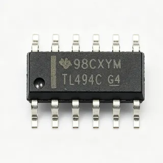
UCC28730-Q1 - PSR Flyback Controller, 5mW Standby | TI
MPN: UCC28730-Q1 ✓ Active| Qty | Unit Price | Extended |
|---|---|---|
| 1 | $1.95 | $1.95 |
| 10 | $1.76 | $17.60 |
| 100 | $1.42 | $142.00 |
| 500 | $1.21 | $605.00 |
| 1,000 | $0.98 | $980.00 |
UCC28730-Q1 Overview
A flyback controller is a switching power supply controller used in isolated DC-DC converters. It regulates output voltage and current by switching the primary-side MOSFET, transferring energy through a coupled inductor to the secondary. Primary-side regulation (PSR) senses the output via an auxiliary flyback winding, eliminating the optocoupler feedback circuit - reducing component count, improving reliability, and lowering standby power within the power management IC hierarchy.
Key features include support for wide input ranges from 40 V to 1000 V DC via appropriate transformer and switch selection, a minimum switching frequency of 30 Hz that enables less than 5 mW no-load standby power, and wake-up signal detection that improves transient response to large load steps. A frequency dithering function reduces EMI for easier conducted-emissions compliance.
Technically, the device uses a proprietary algorithm processing information from the primary power switch current-sense signal and an auxiliary flyback winding to precisely control output voltage and current. Integrated protections include overvoltage, overcurrent, and overtemperature shutdown. AEC-Q100 qualification and a -40C to +150C junction operating range ensure reliable operation in harsh automotive environments such as traction inverters and on-board chargers.
Typical applications include traction-inverter isolated bias supplies, on-board charger (OBC) auxiliary rails, and industrial isolated auxiliary power. A TI reference design delivers an isolated 15 V output at 0.33 A from 40-250 VDC input and 1 A from 250-550 VDC input.
Design tip: ensure tight auxiliary-to-secondary winding coupling for regulation accuracy, and place the current-sense resistor and snubber close to the IC to minimize parasitic inductance and EMI.
Drop-in alternatives for UCC28730-Q1 — same package, pin-to-pin compatible. Different-package parts requiring PCB rework are excluded.
Quick Comparison Tool — Select alternative parts for side-by-side comparison:
UCC28730QDR
✅ Drop-In📋 Reference alternative (not in catalog)
UCC28700QDRQ1
✅ Drop-In📋 Reference alternative (not in catalog)
UCC28700DR
✅ Drop-In ⚠️ Specs Unverified📋 Reference alternative (not in catalog)
UCC28711DR
✅ Drop-In ⚠️ Specs Unverified📋 Reference alternative (not in catalog)
UCC28911DR
✅ Drop-In ⚠️ Specs Unverified📋 Reference alternative (not in catalog)
UCC28730-Q1 Maximum Ratings & Electrical Characteristics
| Topology | Isolated Flyback (PSR) |
| Control Method | Primary-Side Regulation, CV/CC |
| Optocoupler Feedback | Not required |
| Input Voltage Range | 40 V to 1000 V DC (via transformer/switch selection) |
| Switching Frequency Range | 32 Hz to 83 kHz |
| Minimum Switching Frequency | 30 Hz |
| No-Load Standby Power | Less than 5 mW |
| Wake-Up Signal Detection | Yes |
| Frequency Dithering (EMI) | Yes |
| Qualification | AEC-Q100 |
| Junction Temperature Range | -40C to +150C |
| Protection Features | OVP, OCP, Overtemperature Shutdown |
| Package | SOIC (D), 7 pins |
| Mounting Type | Surface Mount |
| RoHS Status | Compliant |
| Reference Design Output | 15 V isolated, 0.33 A at 40-250 VDC / 1 A at 250-550 VDC input |
UCC28730-Q1 Pin Configuration
| Pin 1 | VDD — IC supply voltage from auxiliary winding via bias network |
| Pin 2 | NC — No internal connection |
| Pin 3 | VS — Auxiliary flyback winding voltage sense for PSR output regulation |
| Pin 4 | CS — Primary-side current sense for CC regulation and OCP |
| Pin 5 | GND — Controller ground |
| Pin 6 | NCP — Programming/protection pin (line/cable compensation settings) |
| Pin 7 | DRV — Gate drive output to the primary power MOSFET |
Typical Applications
UCC28730-Q1 is suitable for 6 applications: Traction Inverter Isolated Bias Supply, On-Board Charger (OBC) Auxiliary Power, Industrial Isolated Auxiliary Power, Gate Driver Bias Supplies for SiC/GaN Stages, Smart Meter and E-Meter Power Supply, Battery Formation and Test Equipment Bias.
Traction Inverter Isolated Bias Supply
The UCC28730-Q1 fits traction-inverter bias supplies because its AEC-Q100 qualification, -40C to +150C junction range, and 60-1000 VDC input support cover the high-voltage DC link domain directly. A TI reference design produces three isolated 100 mA outputs from a 60-1000 VDC input using this controller. The PSR topology removes the optocoupler, an automotive reliability concern, while frequency dithering eases conducted-emissions compliance in the noisy inverter environment. Place the controller ground away from gate-drive return paths to keep CS sensing accurate.
Recommended
On-Board Charger (OBC) Auxiliary Power
In on-board chargers, the UCC28730-Q1 generates isolated auxiliary rails for CAN transceivers, microcontrollers, and gate drivers directly from the rectified AC or high-voltage DC bus. Its optocoupler-free PSR feedback reduces BOM count and eliminates a common field-failure component, while less than 5 mW no-load standby supports vehicle sleep-mode current budgets. Wake-up signal detection restores full switching quickly when a load step occurs, maintaining rail accuracy during charger state transitions. The 32 Hz to 83 kHz frequency span lets designers optimize transformer size against light-load efficiency.
Recommended
Industrial Isolated Auxiliary Power
For industrial 400-800 V DC bus systems such as motor drives, servo amplifiers, and energy-storage converters, the UCC28730-Q1 delivers isolated bias power with CV/CC accuracy without an optocoupler. The 40 V to 1000 V DC input capability, achieved through transformer and switch selection, spans low-voltage and high-voltage bus variants on one controller platform. Integrated OVP, OCP, and overtemperature shutdown protect against fault conditions, and frequency dithering reduces EMI filter size. Its sub-5 mW standby suits always-on industrial equipment with aggressive energy-efficiency targets.
Recommended
Gate Driver Bias Supplies for SiC/GaN Stages
The UCC28730-Q1 provides the isolated positive and negative bias rails required by SiC and GaN gate drivers in high-voltage converters. The reference design delivers an isolated 15 V output at up to 1 A from 250-550 VDC input, sufficient for multiple gate-driver channels. PSR regulation with tight auxiliary-to-secondary coupling holds rail accuracy despite wide line and load swings typical of power converters. Because the controller operates from the primary high-voltage side, designers avoid an additional low-voltage standby source, simplifying the bias architecture of wide-bandgap power stages.
Recommended
Smart Meter and E-Meter Power Supply
Smart meters powered from phase voltage benefit from the UCC28730-Q1 optocoupler-free PSR flyback, which produces an isolated low-voltage logic rail directly from the rectified mains. Less than 5 mW no-load standby meets utility idle-consumption limits, and the -40C to +150C junction range covers outdoor meter enclosures. The 30 Hz minimum frequency minimizes no-load energy, while the wake-up detection feature maintains regulation when the RF or display module wakes. Integrated protections reduce the external protection component count in cost-sensitive meter designs.
Recommended
Battery Formation and Test Equipment Bias
Battery formation and ATE systems use the UCC28730-Q1 to derive isolated control and gate-drive bias rails from high-voltage DC buses up to 1000 VDC. Constant-current regulation capability supports charger-style auxiliary outputs, and the wide 32 Hz to 83 kHz frequency range allows compact magnetics in rack-mounted equipment. Frequency dithering helps meet conducted-emissions limits without oversized filters, and the automotive qualification provides headroom for test equipment reused across automotive programs. Ensure the CS resistor and snubber sit close to the IC to limit parasitic ringing at high bus voltages.
Recommended
Recommended Products Summary
Engineering reference data for UCC28730-Q1 — comparison, design guidance, and compliance information.
Selection Guide
Comparison with Alternatives
| Parameter | This Product | UCC28730QDR | UCC28700QDRQ1 | UCC28711DR |
|---|---|---|---|---|
| Package | SOIC-7 (D) | SOIC-7 (D) - same | SOIC-7 (D) - same | SOIC-7 (D) - same |
| Brand | Texas Instruments | Texas Instruments | Texas Instruments | Texas Instruments |
| AEC-Q100 Qualification | Yes | No | Yes | No |
| Regulation Modes | CV + CC | CV + CC | CV + CC | CV + CC |
| Zero-Power Standby (<5 mW) | Yes (30 Hz min frequency) | Yes | No | No |
| Wake-Up Signal Detection | Yes | Yes | No | No |
| Optocoupler-Free PSR | Yes | Yes | Yes | Yes |
Key Differentiators
- Zero-power standby below 5 mW via 30 Hz minimum switching frequency (vs UCC28700QDRQ1)
- Wake-up signal detection for large load-step transient response (vs UCC28711DR)
- Automotive-grade reliability (vs UCC28730QDR)
Design Notes
Place the CS current-sense resistor, VS divider, and RC snubber directly adjacent to the UCC28730-Q1 pins to minimize parasitic inductance in the high dV/dt and dI/dt loops. Keep the gate-drive trace from DRV to the MOSFET short and routed away from the VS sense line. A single-point ground at the CS resistor prevents switching current from modulating the current-sense threshold and corrupting CC regulation accuracy.
Regulation accuracy in PSR designs depends on tight magnetic coupling between the auxiliary winding and the secondary winding. Loose coupling causes leakage-inductance reset error in the VS sampling, shifting output voltage versus load. Specify a transformer with low leakage inductance and verify regulation across line and load on the actual winding stack; do not assume datasheet accuracy without validating the transformer.
Enable the built-in frequency dithering to spread conducted emissions and reduce filter size for CISPR-class compliance in automotive 12/48 V and high-voltage systems. Even with dithering, keep the primary loop (bulk cap, transformer, MOSFET, CS resistor) physically small, and add an RC snubber across the primary winding to clamp leakage-inductance voltage spikes on the DRV drain node.
Size the VDD bias network from the auxiliary winding so VDD remains above the UVLO turn-on threshold at minimum load, since the 30 Hz minimum frequency at no load delivers very little energy per second. If the auxiliary supply cannot sustain VDD at deep standby, add a small trickle charge path from the bulk rail through a high-value resistor.
Compliance Information
AEC-Q100 automotive qualification per TI product page. RoHS and lead-free status per standard TI SOIC (D) offering; REACH and halogen details not stated in provided data.