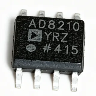
IR2175STRPBF - 600V Linear Current Sense IC, 8-SOIC | Infineon
MPN: IR2175STRPBF ✓ Active| Qty | Unit Price | Extended |
|---|---|---|
| 1 | $3.62 | $3.62 |
| 10 | $3.21 | $32.10 |
| 100 | $2.74 | $274.00 |
| 500 | $2.41 | $1,205.00 |
| 1,000 | $2.09 | $2,090.00 |
IR2175STRPBF Overview
A current sense regulator (also called a linear current sensing IC) is a category of power-management IC that converts a small analog shunt voltage into an isolated, scaled, and noise-immune representation of load current. These ICs sit in the signal chain between a low-side shunt resistor and the controller, providing galvanic isolation between the power stage and logic. The IR2175 family belongs to Infineon's high-voltage gate-driver and sensor portfolio, positioned above simple op-amp current shunts and below isolated delta-sigma modulators.
Key features include 9.5 V to 20 V low-side supply (VCC), 13 V to 20 V high-side floating supply (VB), 2 mA quiescent current on the bootstrap rail (IQBS), 20 mA output current capability, 130 kHz typical PWM output frequency, and ±260 mV input common-mode range with 20 ppm/°C gain temperature drift. An independent fast overcurrent trip signal activates within 2 µs typical delay when the input threshold is exceeded, providing hardware-level short-circuit protection independent of the PWM feedback path.
Architecturally, the IR2175 combines a high-side differential amplifier with an internal level shifter, allowing the low-voltage DSP or MCU to read high-side phase current without external isolation. The monolithic integration of the floating channel eliminates optocoupler drift and propagation delay, supporting high-bandwidth FOC (field-oriented control) loops in variable-frequency drives.
Typical applications include three-phase motor drives, HVAC compressors, industrial servo amplifiers, and EV traction inverters. The wide 600 V floating-channel range covers 230 V and 480 V rectified bus voltages with substantial headroom. Designers select the IR2175 when they need a simple, low-BOM current-feedback path for variable-speed drives.
Designers should size the external shunt to keep peak current below ±260 mV, observe PCB creepage/clearance for the floating pins, and provide adequate bootstrap capacitance to sustain the high-side supply. Compared to discrete op-amp solutions, the IR2175 reduces part count and eliminates calibration of the gain drift.
This page synthesizes distributor pricing, drop-in alternatives, and practical design notes not found in the manufacturer datasheet, helping procurement and firmware teams select, source, and validate a 600 V current-sense IC in a single document.
Drop-in alternatives for IR2175STRPBF — same package, pin-to-pin compatible. Different-package parts requiring PCB rework are excluded.
Variants in this series
Same-series models that are drop-in compatible with IR2175STRPBF (same form factor and footprint) — differing in Package.
Quick Comparison Tool — Select alternative parts for side-by-side comparison:
IR2175SPBF
✅ Drop-In📋 Reference alternative (not in catalog)
IR2175STRPBF-IR
✅ Drop-In📋 Reference alternative (not in catalog)
IR2277SPBF
✅ Drop-In📋 Reference alternative (not in catalog)
IR21771SPBF
✅ Drop-In📋 Reference alternative (not in catalog)
IR2109SPBF
✅ Drop-In✓ In Stock
$1.05 / Unit
View Datasheet →IR2175STRPBF Maximum Ratings & Electrical Characteristics
| Product Type | Linear Current Sensing IC |
| Manufacturer | Infineon (formerly International Rectifier) |
| Package | 8-SOIC (3.90 mm body width) |
| Mounting Type | Surface Mount |
| Output Current | 20 mA |
| VCC Supply Range | 9.5 V to 20 V |
| VB High-Side Floating Supply | 13 V to 20 V (above VS) |
| VS Floating Supply Offset Voltage | 0.3 V to 600 V |
| Differential Input Voltage (VIN+ to VS) | -260 mV to +260 mV |
| Quiescent Current on VB (IQBS) | 2 mA typical |
| Gain Temperature Drift | 20 ppm/°C typical |
| PWM Output Frequency (fO) | 130 kHz typical |
| Overcurrent Trip Delay | 2 µs typical |
| Overcurrent Trip Level | ±260 mV typical |
| Operating Temperature Range | -40 °C to +125 °C |
| Channel Type | Floating high-side (monolithic) |
| Output Type | Digital PWM (open-drain push-pull) |
| Lead Free / RoHS | Lead Free, RoHS Compliant |
| Packaging | Tape & Reel (Digi-Reel) |
IR2175STRPBF Pin Configuration
| Pin 1 | VCC — Low-side and logic fixed supply, 9.5 V to 20 V |
| Pin 2 | IN — Differential current-sense input (to external shunt + terminal) |
| Pin 3 | VS — High-side floating supply return / shunt low-side reference |
| Pin 4 | VB — High-side floating supply (13 V to 20 V above VS) |
| Pin 5 | PWM — Digital PWM output (open-drain, duty cycle proportional to current) |
| Pin 6 | OC — Overcurrent fault output (active when |VIN+ - VS| > 260 mV) |
| Pin 7 | COM — Low-side logic ground reference |
| Pin 8 | NC — Not connected (per datasheet) |
Typical Applications
IR2175STRPBF is suitable for 6 applications: Three-Phase Motor Drive Current Feedback, HVAC Compressor Variable-Frequency Drive, Industrial Servo Amplifier Feedback Path, Solar Inverter Phase Current Monitoring, EV Traction Inverter Current Sense, Uninterruptible Power Supply (UPS) Inverter.
Three-Phase Motor Drive Current Feedback
The IR2175STRPBF sits between the inverter shunt resistor and the microcontroller's timer-capture input in a three-phase motor drive. With a 600 V floating channel and ±260 mV differential input, it tolerates 230 V and 480 V rectified bus voltages while digitizing phase current into a 130 kHz PWM duty cycle. Compared to a discrete op-amp + optocoupler chain, the monolithic integration eliminates calibration of the gain temperature drift (20 ppm/°C typical) and reduces PCB area. The 2 µs overcurrent trip is independent of the feedback PWM and lets a hardware interlock shut down the inverter before the controller reacts, a critical margin in IGBT desaturation events.
Recommended
HVAC Compressor Variable-Frequency Drive
In a residential or commercial HVAC variable-frequency drive, the IR2175STRPBF provides isolated phase-current feedback for field-oriented control of the compressor motor. The 600 V floating channel handles 230 V AC input rectified to ~325 V DC with margin, while the digital PWM output feeds directly into the DSP's capture pin - no external ADC is needed. Designers size the shunt to keep peak phase current below ±260 mV, then count PWM edges in the controller's timer to recover current magnitude. The 2 µs fault path protects the IGBTs from compressor stall or locked-rotor events without firmware latency.
Recommended
Industrial Servo Amplifier Feedback Path
Industrial servo amplifiers demand wide-bandwidth current feedback for accurate torque control. The IR2175STRPBF delivers a 130 kHz PWM output, giving the controller 130 000 current samples per second - sufficient bandwidth for high-dynamics servo loops at rotor speeds up to several thousand RPM. The 20 ppm/°C gain drift keeps measurement accuracy stable across the -40 °C to +125 °C industrial temperature range, eliminating per-axis calibration in volume production. The 8-SOIC package drops into compact servo-board layouts alongside gate drivers and isolated power supplies.
Recommended
Solar Inverter Phase Current Monitoring
In a string inverter or micro-inverter, the IR2175STRPBF monitors the AC-side inductor current for MPPT and grid-synchronization control. The 600 V floating channel covers 480 V AC grid voltages with adequate derating, while the digital PWM output couples to the inverter controller through a single low-cost optocoupler. The 2 mA IQBS quiescent current minimizes losses on the bootstrap supply, important in efficiency-sensitive solar designs. The 2 µs hardware overcurrent trip protects against grid-side short circuits within one line cycle.
Recommended
EV Traction Inverter Current Sense
In an EV traction inverter the IR2175STRPBF provides per-phase current feedback to the motor controller MCU. The 600 V floating channel tolerates 400 V and 800 V traction battery buses (within derating), while the 2 µs overcurrent trip provides hardware desaturation protection in coordination with the gate driver. The 130 kHz PWM output frequency keeps current-loop bandwidth high enough for smooth torque ripple control at low rotor speeds. Designers must observe PCB creepage between the floating pins and the low-voltage logic side per IEC 60664.
Recommended
Uninterruptible Power Supply (UPS) Inverter
In a double-conversion UPS, the IR2175STRPBF senses the inverter-leg current to regulate output voltage and current. The wide 9.5 V to 20 V VCC range operates directly from a 15 V auxiliary rail, while the digital PWM output simplifies isolation to the supervisory DSP. The 2 µs hardware fault trip provides a fast inverter shutdown on output overcurrent or short-circuit, complementing the firmware-based protection. The monolithic 600 V floating channel reduces component count compared to discrete Hall-effect current sensors, saving PCB space and BOM cost.
Recommended
Recommended Products Summary
Engineering reference data for IR2175STRPBF — comparison, design guidance, and compliance information.
Selection Guide
Comparison with Alternatives
| Parameter | This Product | IR2175SPBF | IR21771SPBF | IR2277SPBF | IR2109SPBF |
|---|---|---|---|---|---|
| Brand | Infineon | Infineon | Infineon | Infineon | Infineon |
| Package | 8-SOIC | 8-SOIC - same | 8-SOIC - same | 8-SOIC - same | 8-SOIC - same |
| Function | Current Sense IC | Current Sense IC | Current Sense IC | Current Sense IC | Half-Bridge Gate Driver |
| Floating Channel Voltage | 600 V | 600 V | 600 V | 600 V | 600 V (boot to VS+) |
| Differential Input Range | ±260 mV | ±260 mV | ±260 mV | ±200 mV | N/A (gate driver) |
| Output Format | Digital PWM, 130 kHz | Digital PWM, 130 kHz | Digital PWM, 130 kHz | Digital PWM | Gate-drive HO/LO outputs |
| VCC Supply Range | 9.5 V to 20 V | 9.5 V to 20 V | 9.5 V to 20 V | 9.5 V to 20 V | 10 V to 20 V |
| Unit Price (1 pc) | $3.62 | ~$3.50 | ~$3.80 | ~$3.20 | ~$1.40 |
Key Differentiators
- Monolithic 600 V floating channel eliminates optocoupler isolation chain (vs Discrete op-amp + optocoupler current-sense chain)
- Direct digital PWM output simplifies microcontroller interface (vs Analog-output current sense ICs requiring external ADC)
- Independent 2 µs hardware overcurrent trip runs in parallel to PWM feedback (vs Firmware-only overcurrent detection)
Design Notes
Place the IR2175STRPBF as close as possible to the current-shunt resistor to minimize ground-bounce pickup on the differential IN/VIN pins. Use a Kelvin connection (4-wire) from the shunt to the IC inputs, with traces routed as a tightly-coupled differential pair. Maintain at least 6 mm creepage between the high-side floating pins (VB, VS) and the low-side logic pins (VCC, COM, PWM, OC) per IEC 60664 for 230 V AC and 480 V AC systems.
The IR2175STRPBF draws 2 mA quiescent current from the VB bootstrap rail. Size the bootstrap capacitor Cboot for Cboot >= (IQBS + IIN_bias) × t_on / ΔV, where t_on is the maximum high-side on-time per PWM cycle and ΔV is the allowed droop (typically 0.5 V). For a 10 kHz switching frequency and 50% duty cycle, a 100 nF X7R ceramic in parallel with a 1 µF electrolytic is a robust starting point.
Do not exceed the ±260 mV differential input range - input voltages above this will trigger the overcurrent trip and may saturate the input differential amplifier. For peak phase currents above the maximum shunt-rated value, increase the shunt resistance rather than risk saturating the IR2175. Also ensure the bootstrap diode is a fast-recovery type (tRR < 100 ns); standard rectifiers will overheat at high switching frequency.
Compliance Information
PbF suffix confirms lead-free and RoHS compliance per Infineon product page. Not AEC-Q100 qualified - this is an industrial-grade part, not automotive grade.