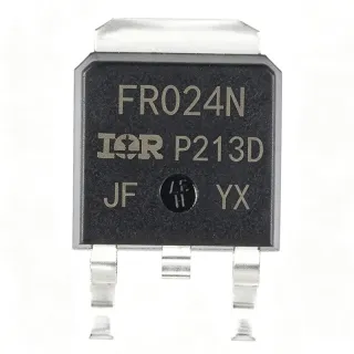
IRFR3607TRPBF - 75V 56A N-Channel HEXFET MOSFET | Infineon | DPAK
MPN: IRFR3607TRPBF ✓ Active| Qty | Unit Price | Extended |
|---|---|---|
| 1 | $2.26 | $2.26 |
| 10 | $1.95 | $19.50 |
| 100 | $1.42 | $142.00 |
| 500 | $0.95 | $475.00 |
| 1,000 | $0.66 | $660.00 |
| 5,000 | $0.39 | $1,950.00 |
IRFR3607TRPBF Overview
A power MOSFET is a voltage-controlled field-effect transistor designed to switch large amounts of current at high efficiency. Within the discrete semiconductor family, MOSFETs sit alongside diodes, IGBTs, and thyristors; they are the workhorse switching element in modern DC-DC converters, motor drives, battery protection circuits, and synchronous rectification stages that replace Schottky diodes to cut conduction losses in low-voltage, high-current rails.
Key specifications include a VDS breakdown of 75V, an on-state resistance of 9 mOhm at VGS=10V / ID=46A, a gate threshold of 4V (typical), a continuous drain current of 56A at case, and a junction-to-case thermal resistance of 1.0 C/W. The device offers fully characterized capacitance and avalanche SOA, providing margin against inductive load transients. The TO-252AA (DPAK) package exposes the drain tab as a thermal pad for direct PCB copper heat spreading.
The HEXFET architecture combines a planar DMOS cell with optimized die area to minimize RDS(on) * Qg figure-of-merit, reducing both conduction and switching losses. Avalanche-rated energy and a wide SOA make the part tolerant of unclamped inductive switching events common in motor and solenoid drive stages.
Typical applications include synchronous rectification in SMPS output stages, high-current DC-DC buck/boost converters, motor control and H-bridge drives, battery management and protection FETs in server/telecom power stages, and low-voltage hot-swap controllers. Pricing is approximately $0.29 (LCSC, as of 2026-08-29) to $2.26 per unit (Infineon, as of 2026-08-29).
When designing with this device, drive the gate with 10V for the lowest RDS(on) and use a substantial copper pour on the drain tab to keep Tj below 125C. Account for bond-wire current derating above 56A continuous.
This page synthesizes distributor pricing, same-package drop-in alternatives, and practical thermal/layout design notes not consolidated in the manufacturer datasheet.
Drop-in alternatives for IRFR3607TRPBF — same package, pin-to-pin compatible. Different-package parts requiring PCB rework are excluded.
Variants in this series
Same-series models that are drop-in compatible with IRFR3607TRPBF (same form factor and footprint) — differing in Technology, Drain-Source Voltage (VDS), Package, Avalanche Rated, Lead-Free / RoHS.
Quick Comparison Tool — Select alternative parts for side-by-side comparison:
IRFR3607TRPBF-Q1
✅ Drop-In📋 Reference alternative (not in catalog)
IRFR3806TRPBF
✅ Drop-In✓ In Stock
$0.52 / Unit
View Datasheet →IRFR2405TRLPBF
✅ Drop-In✓ In Stock
$0.55 / Unit
View Datasheet →IRFR1205TRPBF
✅ Drop-In✓ In Stock
$0.49 / Unit
View Datasheet →IRFR4620TRLPBF
✅ Drop-In✓ In Stock
$1.72 / Unit
View Datasheet →IRLR2905TRPBF
✅ Drop-In✓ In Stock
$0.61 / Unit
View Datasheet →IRFR3607TRPBF Maximum Ratings & Electrical Characteristics
| Polarity / Channel Type | N-Channel |
| Drain-to-Source Voltage (VDS) | 75 V |
| Continuous Drain Current (ID, Tc) | 56 A |
| Calculated Die Drain Current | 80 A |
| On-State Resistance (RDS(on)) | 9 mOhm @ VGS=10V, ID=46A |
| Gate Threshold Voltage (VGS(th)) | 4 V |
| Total Gate Charge (Qg) | 56 nC |
| Gate-to-Source Voltage (VGS) Max | +/-20 V |
| Power Dissipation (PD, Tc) | 140 W |
| Thermal Resistance (RthJC) | 1.0 C/W |
| Operating Temperature Range | -55C to +175C (TJ max 175C per datasheet convention) |
| Package | TO-252AA (DPAK) |
| Mounting Type | Surface Mount |
| Technology | IR HEXFET (planar DMOS) |
| Avalanche SOA | Fully characterized |
| RoHS / Lead-Free | Compliant / Pb-free (PBF suffix, JESD-609 e3) |
IRFR3607TRPBF Pin Configuration
| Pin 1 | Gate — Gate drive input; drive with 10V for lowest RDS(on) |
| Pin 2 | Drain — Drain terminal; also electrically bonded to the rear metal tab |
| Pin 3 | Source — Source terminal; connect to circuit reference and Kelvin-source if available |
| Pin Tab | Drain (TAB) — Rear metal tab electrically common with Pin 2 (Drain); serves as primary thermal path and should be soldered to PCB copper pour |
Safe Operating Area (DC, Tj=25C)
Typical Applications
IRFR3607TRPBF is suitable for 6 applications: Synchronous Rectification in SMPS, High-Current DC-DC Buck/Boost Converters, Motor Control and H-Bridge Drives, Battery Management and Protection FETs, Hot-Swap and Inrush Current Limiting, Industrial Solenoid and Relay Drivers.
Synchronous Rectification in SMPS
The IRFR3607TRPBF's 9 mOhm RDS(on) at VGS=10V and 56 nC total gate charge make it an excellent synchronous rectifier in 48V-input isolated and non-isolated SMPS. The HEXFET cell delivers the low conduction loss required at the output rectifier position, while the 75V VDS rating provides margin against ringing on 36-48V bus rails. Designers typically pair this part with a dedicated gate-driver IC (e.g., UCC27211) and place two IRFR3607 in parallel for >50A output stages where Schottky diodes would otherwise dominate losses.
Recommended
High-Current DC-DC Buck/Boost Converters
In hard-switched buck and boost converters operating at 100 kHz to 1 MHz, the IRFR3607TRPBF's combination of 9 mOhm RDS(on) and 56 nC Qg keeps total switching + conduction loss competitive. The 75V VDS provides ample headroom for 24V and 36V automotive/industrial input rails, and the fully characterized avalanche SOA protects against inductor kickback during fault conditions. For multi-phase VRMs, multiple IRFR3607 in parallel achieve >100A per phase with manageable thermal rise on the drain-tab copper pour.
Recommended
Motor Control and H-Bridge Drives
The IRFR3607TRPBF is well suited to brushed DC motor H-bridge and half-bridge driver stages in 24V-48V systems such as e-bikes, power tools, and industrial actuators. The 56A continuous rating supports motors up to ~1.5 kW without paralleling, while the 9 mOhm RDS(on) limits conduction loss during PWM operation at 20-50 kHz. The fully characterized avalanche energy rating absorbs the back-EMF spike during PWM commutation, eliminating the need for external snubbers in most 24V applications.
Recommended
Battery Management and Protection FETs
In 24V-48V battery packs for telecom backup, e-scooters, and light EVs, the IRFR3607TRPBF serves as the high-side or low-side protection MOSFET. The 9 mOhm RDS(on) reduces steady-state voltage drop across the protection FET, preserving battery runtime, while the 75V VDS handles transient surges during load steps. The PBF suffix confirms Pb-free termination for direct use in consumer and industrial battery products. Battery-pack designers typically derate to 30-40A continuous to keep junction temperature rise below 50C.
Recommended
Hot-Swap and Inrush Current Limiting
The IRFR3607TRPBF's 75V VDS and 56A rating make it a strong candidate for 24V-48V hot-swap controllers in server, telecom, and industrial plug-in cards. The 9 mOhm RDS(on) limits steady-state voltage drop after the inrush transient subsides, and the avalanche-rated SOA absorbs the energy stored in the backplane bulk capacitors during hot-plug events. Paired with a hot-swap controller IC, the IRFR3607 enables >50A continuous card power with controlled turn-on and overcurrent protection.
Recommended
Industrial Solenoid and Relay Drivers
In industrial solenoid valves, relay coils, and contactor drivers operating at 24V-48V DC, the IRFR3607TRPBF serves as a low-side switch with built-in avalanche ruggedness. The 9 mOhm RDS(on) minimizes steady-state power dissipation, while the 75V VDS rating comfortably absorbs the inductive kickback spike when the solenoid de-energizes. The DPAK package allows automated assembly and good thermal performance when soldered to a 1-2 square inch copper pad, supporting reliable operation in factory automation environments.
Recommended
Recommended Products Summary
Engineering reference data for IRFR3607TRPBF — comparison, design guidance, and compliance information.
Selection Guide
Comparison with Alternatives
| Parameter | This Product | IRFR3607TRPBF-Q1 | IRFR3806TRPBF | IRFR2405TRLPBF | IRFR1205TRPBF | IRFR4620TRLPBF | IRLR2905TRPBF |
|---|---|---|---|---|---|---|---|
| Brand | Infineon | Infineon | Infineon | Infineon | Infineon | Infineon | Infineon |
| Package | TO-252AA (DPAK) | TO-252AA (DPAK) - same | TO-252AA (DPAK) - same | TO-252AA (DPAK) - same | TO-252AA (DPAK) - same | TO-252AA (DPAK) - same | TO-252AA (DPAK) - same |
| VDS (Drain-to-Source Voltage) | 75 V | 75 V | 60 V | 55 V | 55 V | 200 V | 55 V |
| Continuous Drain Current (ID, Tc) | 56 A | 56 A | 80 A (package-limited) | ~70 A (package-limited) | ~30 A (package-limited) | ~24 A (package-limited) | ~42 A (package-limited) |
| RDS(on) @ VGS=10V | 9 mOhm | 9 mOhm | 7.6 mOhm | ~8 mOhm | ~24 mOhm | ~80 mOhm | ~27 mOhm |
| Gate Threshold Voltage (VGS(th)) | 4 V | 4 V | ~3 V | ~3 V | ~3 V | ~3 V | ~1.4 V (logic-level) |
| RthJC (Thermal Resistance Junction-Case) | 1.0 C/W | 1.0 C/W | 1.0 C/W | 1.0 C/W | 1.67 C/W | 1.0 C/W | 1.67 C/W |
| Automotive Grade (AEC-Q100) | No (commercial) | Yes (AEC-Q100 qualified) | No | No | No | No | No |
Key Differentiators
- Optimized 75V VDS for 48V telecom/industrial bus rails (vs IRFR2405TRLPBF)
- Lower RDS(on) than logic-level alternatives at full 10V gate drive (vs IRLR2905TRPBF)
- Wide process-portfolio support within Infineon's IR HEXFET family (vs Cross-brand 75V DPAK MOSFETs)
Design Notes
Estimated: at ID=30A continuous, RDS(on)=9 mOhm, conduction loss is P=I^2*R = 30^2 * 0.009 = 8.1W. With RthJC=1.0 C/W and assuming RthJA=50 C/W on a 1 sq inch DPAK copper pour, total RthJA-amb is ~51 C/W and junction temperature rise above ambient is 8.1W * 51 C/W = 413C - clearly above the 175C limit. This illustrates that continuous current must be kept well below 56A in real layouts. Always derate to 20-30A continuous in typical DPAK designs without external heatsinking, and size the drain-tab copper pour to at least 1 square inch of 2oz copper.
Solder the DPAK drain tab directly to a PCB copper pour that is on the top layer (or inner layer with thermal vias) and connects to the drain circuit node. Use a minimum 1 square inch of 2oz copper for thermal spreading; for sustained currents above 20A, use 2-4 square inches and an array of thermal vias (0.3mm drill, 1mm pitch) under the tab. Place gate-drive traces as short and wide as possible to minimize gate-loop inductance, and add a 10-100 Ohm gate-source resistor to prevent unintended turn-on from drain-voltage transients (Miller effect).
Do not drive the gate below 10V expecting low RDS(on) - the 4V gate threshold means RDS(on) at 4.5V (logic-level drive) is several times higher than at 10V, leading to unexpected thermal runaway. Do not exceed VGS=+/-20V or the gate oxide will be damaged. Do not parallel multiple IRFR3607 devices without external gate-source resistors (10-100 Ohm each) - otherwise MOSFET oscillation at hundreds of MHz can destroy the parts. Finally, do not operate continuously at 56A in a DPAK without substantial heatsinking; the bond-wire limit, not the silicon, is the true constraint.
Keep the high-current loop (drain-source-load-return) as small as physically possible to minimize parasitic inductance that causes VDS overshoot during switching. Place the gate driver IC within 5mm of the gate pin, and route the gate trace over a continuous ground plane to limit coupling from the drain-switching node. For synchronous rectifier stages, place the high-side and low-side FETs symmetrically and minimize the dead-time region in the gate-driver IC to limit body-diode conduction loss.
Compliance Information
Pb-free per JESD-609 e3 (PBF suffix). RoHS compliant per Infineon product page. Not AEC-Q100 qualified in the standard part; the IRFR3607TRPBF-Q1 variant is AEC-Q100 qualified for automotive applications. Halogen-free and REACH compliant per Infineon product disclosures.