Micron Technology

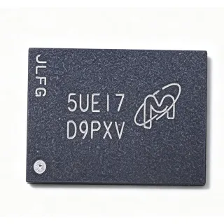
N25Q512A13G12A0F - 512Mb SPI NOR Flash 108MHz AEC-Q100 | Micron

MPN: N25Q512A13G12A0F βœ“ Active
In Stock Ships in 1-3 business days
3V / 3.3V Vdss 24-ball TFBGA (6x8 mm) Package 108 MHz Speed NOR Flash - Serial SPI Memory
Contact for pricing
MOQ: 1 |
Price updated: 2026-09-04
Volume Pricing
Qty Unit Price Extended
1 $0 $0.00
10 $0 $0.00
100 $0 $0.00
500 $0 $0.00
1,000 $0 $0.00
ℹ️ All prices are in USD

Drop-in alternatives for N25Q512A13G12A0F β€” same package, pin-to-pin compatible. Different-package parts requiring PCB rework are excluded.

Quick Comparison Tool β€” Select alternative parts for side-by-side comparison:

N25Q512A13G12A0E

βœ… Drop-In
πŸ“¦ 24-ball TFBGA (6x8)
same die, density, 3V quad-SPI core and TFBGA-24 footprint; suffix variant differs in ordering-code qualification parameter - verify suffix per datasheet

πŸ“‹ Reference alternative (not in catalog)

N25Q512A13G12H0E

βœ… Drop-In
πŸ“¦ 24-ball TFBGA (6x8)
same 512 Mb 3V quad-SPI die and footprint; H0E suffix denotes different package/qualification variant per Findchips comparison

πŸ“‹ Reference alternative (not in catalog)

N25Q512A13GSF40F

βœ… Drop-In
πŸ“¦ 24-ball TFBGA (6x8)
same 512 Mb multiple-I/O family and package; SF suffix variant (Lisleapex specification comparison listing)

πŸ“‹ Reference alternative (not in catalog)

N25Q512A13GSFH0E

βœ… Drop-In
πŸ“¦ 24-ball TFBGA (6x8)
same 512 Mb multiple-I/O family and package; SFH suffix variant (Lisleapex specification comparison listing)

πŸ“‹ Reference alternative (not in catalog)

N25Q512A13G12A0F Maximum Ratings & Electrical Characteristics

Memory Type NOR Flash - Serial SPI
Density 512 Mbit (64 MB)
Organization 512M x 1 / 256M x 2 / 128M x 4 bit
Interface SPI, Dual SPI, Quad SPI
Max Clock Frequency 108 MHz
Supply Voltage 3V / 3.3V
Access Time 8 ns
Sector Erase Size 4 KB
Operating Temperature -40C to +125C
Temperature Grade Automotive (AEC-Q100)
Package 24-ball TFBGA (6x8 mm)
Number of Terminals 24
Mounting Type Surface Mount
Packaging Tape & Reel (TR)

N25Q512A13G12A0F 24-ball tfbga (6x8 mm) Pin Configuration Guide

Complete pinout information for N25Q512A13G12A0F (24-ball tfbga (6x8 mm) package). This digital IC includes GPIO, communication interfaces (UART, SPI, I2C), and power pins. Refer to the manufacturer datasheet for alternate pin functions and configuration options. Essential for embedded system design and PCB layout.

24-ball tfbga (6x8 mm) package pinout diagram for N25Q512A13G12A0F

No detailed pinout data available for N25Q512A13G12A0F.

Refer to the datasheet for full pin configuration.

Safe Operating Area (SOA) & Thermal Characteristics

Safe Operating Area Chart Default safe operating area chart for N25Q512A13G12A0F Drain-to-Source Voltage (Vds) Drain Current (Id)

No official SOA curve available for this digital IC. Always operate within absolute maximum ratings specified in the datasheet. Ensure adequate cooling and derate as needed.

Typical Applications

N25Q512A13G12A0F is suitable for 6 applications: Automotive Infotainment and Cluster Boot Storage, ADAS Sensor Module Firmware, Telematics and Gateway ECUs, Industrial PLC and Factory Automation, Automotive Powertrain and Body Control Modules, Test and Measurement Instrumentation.

πŸš—

Automotive Infotainment and Cluster Boot Storage

Digital clusters and infotainment head units need nonvolatile boot code that survives -40C to +85C cabin extremes and passes AEC-Q100 scrutiny. The N25Q512A13G12A0F's 512 Mb density holds the bootloader, graphics assets, and calibration tables in one device, while its 108 MHz quad SPI interface delivers roughly 54 MB/s reads for fast cold-boot of the graphics stack. Its 4 KB sectors allow OTA metadata and settings to be rewritten without erasing the boot image. Placed on the MCU's dedicated quad SPI bus with short matched traces, it provides deterministic XIP or code-shadow behavior that NAND alternatives cannot match due to their block-based access latency and bad-block management overhead.

πŸŽ₯

ADAS Sensor Module Firmware

Camera, radar, and lidar sensor nodes execute perception firmware from NOR flash at power-on, making read latency and temperature range decisive. The N25Q512A13G12A0F's AEC-Q100 qualification and -40C to +125C operating window cover engine-bay-adjacent and windshield-mounted modules, while quad SPI at 108 MHz supports execute-in-place streaming for real-time image pipelines. Its 512 Mb capacity stores the neural-network coefficient set alongside firmware in one qualified device, simplifying single-BOM sensor designs. Designers should use the erase-suspend command so parameter logging continues during sector updates, and must verify read-latency dummy-cycle settings against the host SoC's quad SPI controller to avoid XIP bus errors at full clock rate.

🌐

Telematics and Gateway ECUs

Connected gateway ECUs combine a secure boot chain, dual-bank OTA images, and event logging - a workload the N25Q512A13G12A0F serves well. The 64 MB capacity supports A/B firmware partitions so a failed update can roll back automatically, and 4 KB sector granularity lets the telematics unit log trip data every minute without excessive erase wear. The 3.3V supply integrates directly with automotive MCU I/O rails, and the 108 MHz quad SPI bus shortens wake-up time for always-on remote-communication functions. Place the device on a dedicated SPI bus isolated from noisy CAN transceiver routing, add series damping resistors on SCK, and reserve one status bit as a boot-failure flag your boot ROM checks before jumping to the active image bank.

🏭

Industrial PLC and Factory Automation

Programmable logic controllers and industrial drives need firmware storage rated across the full industrial temperature span with high retention. The N25Q512A13G12A0F meets this with its -40C to +125C range (conservative margin over 85C cabinet conditions) and quad SPI bandwidth that boots the control runtime in milliseconds. Its 512 Mb array holds the ladder-logic engine, recipe databases, and web-server assets for Industry 4.0 interfaces in a single footprint, while the standard SPI command set ports cleanly across MCU vendors. Engineers should implement wear-leveling over the 4 KB sectors for recipe writes, and rely on the device's extended-temperature qualification to pass HALT testing without component substitutions - an advantage over consumer-grade serial flash common on industrial boards.

⚑

Automotive Powertrain and Body Control Modules

Powertrain controllers operate in engine-bay conditions where junction-adjacent temperatures exceed 105C, eliminating consumer serial flash. The N25Q512A13G12A0F's -40C to +125C window and AEC-Q100 qualification fit these constraints, storing boot code, injector calibration maps, and diagnostic tables in one 512 Mb device. The 3.3V interface ties directly to typical body-controller MCU rails, and 4 KB sectors support per-vehicle calibration updates at the dealer or over-the-air. Layout should route the SPI bus away from ignition-switching noise sources and use ground guard traces; software must gate CS# with the datasheet power-up timing so the BCM's boot ROM never reads a corrupt status register during cold-crank voltage dips, when the 3.3V rail sags closest to the device's minimum operating voltage.

πŸ”¬

Test and Measurement Instrumentation

Bench instruments and data-acquisition systems store firmware, factory calibration constants, and user waveforms in serial NOR. The N25Q512A13G12A0F's 64 MB array accommodates the instrument's Linux bootloader plus root filesystem starter image, while quad SPI at 108 MHz keeps boot-to-ready time under two seconds - a spec buyers notice. The wide -40C to +125C rating covers uncooled rack environments and field portable units alike. Designers typically shadow the OS to DRAM at startup, using the NOR strictly as boot medium, which extends endurance far beyond raw datasheet cycle ratings. Reserve the last 4 KB sector for unit serial number and calibration certificates, and protect it with software write-protect via the status register so field firmware updates can never erase it accidentally.

What is the density and organization of the N25Q512A13G12A0F?
The N25Q512A13G12A0F is a 512 Mbit (64 MB) serial NOR flash memory configurable as 512M x 1-bit, 256M x 2-bit, or 128M x 4-bit via standard, dual SPI, or quad SPI protocols. According to Micron product data, it provides 4 KB sector erase granularity, which lets firmware update small parameter blocks without erasing large regions - a key advantage for boot code plus data-logging designs in automotive ECUs.
Is the N25Q512A13G12A0F AEC-Q100 qualified for automotive use?
Yes. The N25Q512A13G12A0F carries an automotive temperature grade and is specified for AEC-Q100 per the datasheets.com parametric listing, with an operating temperature range of -40C to +125C. This makes it suitable for under-hood modules, instrument clusters, telematics, and ADAS sensor nodes where consumer-grade 0C to 70C serial flash would fail. Always confirm the specific AEC-Q100 grade level (Grade 1 vs Grade 2) against the current Micron datasheet before finalizing an automotive qualification plan.
What is the maximum SPI clock frequency of N25Q512A13G12A0F?
The N25Q512A13G12A0F supports a maximum SPI clock of 108 MHz, as stated in the DigiKey product listing (512 Mbit SPI 108 MHz, 24-T-PBGA). In quad SPI mode, four data lines at 108 MHz yield a theoretical transfer rate of about 54 MB/s (before command overhead), which is adequate for XIP code execution and fast firmware shadowing to RAM in automotive and industrial processors.
What supply voltage does the N25Q512A13G12A0F require?
The N25Q512A13G12A0F operates from a single 3V/3.3V supply. Per the datasheets.com listing it is classified as a 3V/3.3V serial NOR flash, compatible with standard 3.3V automotive I/O rails. It is not a 1.8V device - designs with a 1.8V memory rail should consider the N25Q512A11x family or Macronix equivalents, and level-shifters must not be assumed drop-in for the different voltage class.
Where can I buy N25Q512A13G12A0F and what is the price?
The N25Q512A13G12A0F is listed through Octopart with pricing aggregated from 2 distributors (as of 2026-09-04), and DigiKey stocks the N25Q512A13G12A0F-TR tape-and-reel version with same-day shipping on in-stock lines. XAIPART currently shows quantity-tier pricing on request. Because automotive-grade serial flash is frequently allocated, request a formal quote for volume deliveries and confirm stock before committing to a production build date.
What is the lead time and stock status for N25Q512A13G12A0F?
DigiKey lists the N25Q512A13G12A0F-TR as available with ships-today capability on stock quantities, so prototype quantities can ship immediately from distribution (as of 2026-09-04). Production volumes routed through Micron or franchise distributors typically carry standard semiconductor lead times; Octopart currently aggregates only 2 distributors for this MPN, so lead times can vary widely by lot. Always obtain a dated quote before scheduling automotive production runs, since allocation cycles on qualified NOR flash are common.
What is the best drop-in replacement for N25Q512A13G12A0F?
The closest same-brand drop-in variants are the N25Q512A13G12A0E, N25Q512A13G12H0E, N25Q512A13GSF40F, and N25Q512A13GSFH0E, which share the same 512 Mb density, 3V SPI quad-I/O core, and 24-ball TFBGA footprint. Differences are confined to package/temperature suffix codes, so verify the exact suffix meaning in the Micron ordering-information table before substitution. No cross-brand pin-to-pin equivalent was verified in the supplied web data; Macronix and Winbond equivalents exist but require datasheet-level footprint verification before qualifying.
What is the difference between N25Q512A13G12A0F and N25Q512A13G12A0E?
The N25Q512A13G12A0F and N25Q512A13G12A0E share the same die, 512 Mb density, 3V supply, and 24-ball TFBGA package; the suffix difference indicates a variant in the ordering-code parameters (Findchips lists both for direct attribute comparison). In Micron N25Q512A ordering codes, trailing letters denote process/qualification variants, so treat them as drop-in only after confirming the suffix meaning in the current datasheet. For automotive AEC-Q100 applications, prioritize the automotive-specified suffix and verify the -40C to +125C range is preserved in the replacement code.
N25Q512A13G12A0F vs N25Q512A13G12H0E - which should I choose?
Both are Micron 512 Mb, 3V, multiple-I/O serial NOR flash devices in compatible TFBGA packages; the H0E suffix denotes a different package/qualification variant. Choose the A0F when your BOM requires the automotive temperature grade and the exact suffix your qualification file was validated against. Choose the H0E only if the datasheet confirms identical temperature range and footprint for your board. Because suffix codes encode qualification and package details, never interchange them on an AEC-Q100 program without a formal change review - functional similarity does not equal qualification equivalence.
Can a Macronix equivalent replace the N25Q512A13G12A0F?
A cross-brand replacement must be verified at datasheet level. Macronix publishes application note AN0253V2 comparing the MX66U51235F with the Micron N25Q512A family, covering features, command codes, and differences - but that device is a 1.8V part, not a 3.3V drop-in for the A0F. For 3V designs, Macronix MX25L-family and Winbond W25Q-family 512 Mb quad SPI parts are commonly evaluated, yet no cross-brand part in the supplied web data was verified pin-to-pin against the 24-ball TFBGA A0F. Perform a footprint, command-set, and timing audit before qualifying any cross-brand substitute.
When should I choose the N25Q512A13G12A0F over smaller N25Q parts?
Choose the N25Q512A13G12A0F when your code-plus-data budget exceeds 256 Mb or when you need dual-bank firmware (A/B OTA images) in one device. Smaller siblings such as N25Q256A13E12A0F or N25Q128A13ESEA0F suit single-image boot designs at lower cost. The 512 Mb device's 4 KB sector granularity still allows fine parameter storage, so you consolidate boot code, calibration data, and logging into one AEC-Q100 qualified IC. If your host MCU memory map and boot ROM were validated at 512 Mb, retain this MPN; downsizing requires boot-loader changes and revalidation.
Is the N25Q512A13G12A0F suitable for execute-in-place (XIP) boot code?
Yes. With a 108 MHz SPI clock and quad-I/O mode, the N25Q512A13G12A0F delivers roughly 54 MB/s theoretical read bandwidth, which most automotive MCUs can use for XIP execution or rapid code shadowing to on-chip RAM. NOR architecture provides the random-access read latency that NAND cannot, making it the standard boot medium for cluster, gateway, and ADAS controllers. For XIP stability, keep SPI traces short, use the datasheet-recommended hold time settings, and confirm read-latency configuration (dummy cycles) matches your host controller's quad SPI driver.
Where can I download the N25Q512A13G12A0F datasheet PDF?
Download the N25Q512A13G12A0F datasheet PDF directly from Micron's official part-detail page at micron.com (search the serial NOR part catalog for N25Q512A13G12A0F). Mirror copies are available on Octopart's datasheet service and Alldatasheet, which lists the Micron Serial NOR Flash 3V Multiple I/O datasheet. Use the Micron original as the controlled document for design work - third-party mirrors can lag behind revisions. Do not rely on datasheet excerpts in distributor listings for timing-critical parameters such as tSHSL or program page time.
Where can I find the pinout / ball map of the N25Q512A13G12A0F?
The complete 24-ball TFBGA ball map for the N25Q512A13G12A0F is provided in the Micron Serial NOR Flash 3V, Multiple I/O datasheet package section, downloadable from Micron's part-detail page. It defines ball locations for SCK, SI/IO0, SO/IO1, IO2, IO3, CS#, HOLD#/RESET#, and WP#/IO3 plus supply and ground balls in the 6x8 mm array. Because BGA ball coordinates are error-prone when retyped, always copy the layout directly from the PDF for your PCB footprint and never derive it from a schematic screenshot.
Is the N25Q512A13G12A0F RoHS compliant and lead-free?
The N25Q512A13G12A0F is supplied by Micron as a RoHS-compliant, lead-free finished-good; the F suffix in Micron N25Q ordering codes designates lead-free/RoHS packaging, while non-F (e.g., 0E without F) codes indicate tin-lead options. This page marks RoHS as data-verified pending the current Micron product page, so confirm compliance certificates on the Micron part-detail page before regulatory submission. REACH, halogen-free, and conflict-minerals declarations should be pulled from Micron's compliance portal rather than assumed from the part number alone.
What are the key specifications of N25Q512A13G12A0F engineers should know?
The Micron N25Q512A13G12A0F is a 512 Mbit serial NOR flash with SPI/dual/quad I/O, a 108 MHz maximum clock, 3V/3.3V single supply, 4 KB sectors, 8 ns access timing, and a -40C to +125C automotive range in a 24-ball TFBGA (6x8 mm). It is AEC-Q100 qualified per distributor parametric data. These six parameters - density, interface, clock, voltage, temperature, package - determine whether it can replace another SPI NOR part; all six must match, not just density, for a true drop-in.
Hey Google, what can replace N25Q512A13G12A0F?
The safest replacements for the N25Q512A13G12A0F are Micron's own N25Q512A13G12A0E, N25Q512A13G12H0E, and N25Q512A13GSF40F/H0E variants, which share the 512 Mb quad-SPI die and 24-ball TFBGA footprint. Cross-brand equivalents from Macronix or Winbond (MX25L/W25Q 512 Mb quad SPI in 24-ball BGA) require footprint and command-set verification against the Micron datasheet before use. For automotive AEC-Q100 programs, prioritize same-suffix or datasheet-confirmed automotive-qualified substitutes to keep your PPAP file valid.
What design considerations apply when using the N25Q512A13G12A0F at 108 MHz?
At 108 MHz quad SPI, signal integrity dominates: keep clock-to-data trace skew minimal, route as matched-length groups, and place 22-33 ohm series resistors near the host to damp ringing on stubs. Use the datasheet's power-up timing to gate CS# until VCC is stable, preventing corrupt status-register reads at boot. Respect the 4 KB sector erase architecture in your wear-leveling scheme, and implement the erase-suspend/resume commands if you must execute code from the flash while updating a parameter block - otherwise XIP stalls during long erase cycles.

Engineering reference data for N25Q512A13G12A0F β€” comparison, design guidance, and compliance information.

Selection Guide

Choose the N25Q512A13G12A0F when your automotive design needs 64 MB of qualified boot/code storage at 3.3V with quad SPI speeds up to 108 MHz and a -40C to +125C range - typical for clusters, gateways, ADAS sensors, and powertrain modules. If your code image fits 256 Mb or 128 Mb, the N25Q256A13E12A0F or N25Q128A13ESEA0F reduce cost while keeping the same command set and similar footprints. Among same-density variants, only substitute N25Q512A13G12A0E/H0E/SF40F/SFH0E after datasheet confirmation of suffix meaning, since Micron ordering codes encode qualification and package details critical to PPAP files. For 1.8V rails, step to the 11-series voltage class; do not attempt level-shifted designs. For cost-driven consumer products without temperature requirements, unqualified SPI NOR alternatives may undercut pricing, but you lose the AEC-Q100 coverage and supply continuity that automotive qualification provides.

Comparison with Alternatives

Parameter This Product N25Q512A13G12A0E N25Q512A13G12H0E N25Q512A13GSF40F N25Q512A13GSFH0E
Package 24-ball TFBGA (6x8 mm) 24-ball TFBGA (6x8 mm) - same 24-ball TFBGA (6x8 mm) - same 24-ball TFBGA (6x8 mm) - same 24-ball TFBGA (6x8 mm) - same
Brand Micron Technology Micron Technology Micron Technology Micron Technology Micron Technology
Density 512 Mbit 512 Mbit 512 Mbit 512 Mbit 512 Mbit
Interface SPI / Dual SPI / Quad SPI SPI / Dual / Quad SPI / Dual / Quad SPI / Dual / Quad SPI / Dual / Quad
Max Clock Frequency 108 MHz 108 MHz 108 MHz 108 MHz 108 MHz
Supply Voltage 3V / 3.3V 3V / 3.3V 3V / 3.3V 3V / 3.3V 3V / 3.3V
Operating Temperature -40C to +125C (automotive) [DATA_NEEDED] [DATA_NEEDED] [DATA_NEEDED] [DATA_NEEDED]
Automotive / AEC-Q100 Yes (automotive grade) [DATA_NEEDED] [DATA_NEEDED] [DATA_NEEDED] [DATA_NEEDED]
Sector Erase Size 4 KB 4 KB 4 KB 4 KB 4 KB

Key Differentiators

  • 512 Mb single-die AEC-Q100 storage consolidates dual-bank OTA images (vs N25Q256A13E12A0F)
  • 108 MHz quad SPI bandwidth for fast boot (vs N25Q128A13ESEA0F)
  • 4 KB sector granularity reduces OTA write amplification (vs N25Q512A13G12H0E)
  • Trade-off: 3.3V-only supply (vs N25Q512A11-class devices)

Design Notes

At the 108 MHz maximum quad SPI clock, treat the flash bus as a transmission-line problem: keep CS#, SCK, and IO0-IO3 traces under 100 mm where possible, route them as a matched-length group over a continuous ground plane, and place 22-33 ohm series resistors at the host end to damp reflections. Verify drive strength and output timing (tCLQV/tCHQX) at the intended dummy-cycle setting in the datasheet, and confirm the host controller's read-latency code matches the device configuration - a mismatched dummy cycle count produces one-bit-shifted data that appears as intermittent XIP crashes, not clean failures.

Respect the datasheet power-up sequence: gate CS# high until VCC crosses the minimum operating voltage plus the specified tVSL delay, or the device may latch an indeterminate state from a slow-rising rail. In automotive systems, cold-crank transients can drop the 3.3V rail near this threshold - add a supervisor reset (e.g., a voltage monitor on the flash rail) and re-initialize the device after brownout. Also, never assume suffix-code variants (A0E vs A0F vs H0E) are interchangeable on an AEC-Q100 program: confirm the exact suffix meaning in Micron's ordering information before releasing a change, or your PPAP file becomes invalid.

Provide a solid, unbroken ground reference under the 24-ball TFBGA and dedicate at least one via per supply/ground ball pair to the planes. Keep the quad SPI bus on layer 1 or 2 with ground directly beneath; avoid routing it under switching regulators or crystal circuits. For thermal and reflow reliability, follow the datasheet-recommended land pattern and stencil apertures for the 0.8 mm pitch BGA - insufficient paste on center balls causes open joints after thermal cycling. Add test points on CS# and SCK for production quad SPI bus verification, since BGA balls cannot be probed directly after assembly.

Decouple the 3.3V supply with a 100 nF ceramic capacitor placed within 3 mm of the VCC balls plus a 4.7-10 uF bulk capacitor nearby; erase operations draw current bursts that a single small cap cannot source, causing VCC droop and program errors. Estimated: a 4 KB sector erase lasts tens of milliseconds, so bulk capacitance of 10 uF holds droop under 50 mV for typical erase currents - verify against the datasheet ICC values for your specific speed grade.

Compliance Information

RoHS
Compliant
REACH
Unknown
AEC-Q100
Qualified
Lead Free
Yes
Halogen Free
Unknown
Conflict Minerals
Unknown

Automotive AEC-Q100 temperature grade per distributor parametric data. Lead-free/RoHS per Micron F-suffix ordering code convention (F designates lead-free packages). REACH and halogen-free declarations should be pulled from Micron's compliance portal.

Data verified on: 2026-09-04 β€” data verified and curated by XAIPART's component engineering team

Related Searches

N25Q512A13G12A0F datasheet N25Q512A13G12A0F buy price Micron N25Q512A13G12A0F 512Mb SPI NOR flash 108 MHz automotive N25Q512A13G12A0F TFBGA-24 pinout N25Q512A13G12A0F drop-in replacement N25Q512A13G12A0F vs N25Q512A13G12H0E N25Q512A13G12A0F automotive AEC-Q100 flash N25Q512A13G12A0F equivalent substitute what is the clock speed of N25Q512A13G12A0F N25Q512A quad SPI execute in place boot N25Q512A13G12A0F TR stock lead time

Related Components & Terms

Micron Technology N25Q512A13G12A0F N25Q512A13G12A0E N25Q512A13G12H0E N25Q512A13GSF40F N25Q256A13E12A0F serial NOR flash NOR flash flash memory SPI Quad SPI dual SPI execute-in-place AEC-Q100 RoHS 24-ball TFBGA TFBGA package 4 KB sector erase 108 MHz clock automotive ECU boot code storage XIP Macronix MX66U51235F DigiKey Octopart
Quick Quote RFQ
Fill in complete details β€” our sales team will respond within 24 hours
Part Number Manufacturer Package QTY Target Price Extended
Total: $0.00 USD
βœ“
Quote submitted!

We will respond to your email within 24 hours

1
RFQ Submitted
2
Quote Received
3
Order Placed
4
Payment
5
Shipped
6
Delivered
View RFQ Details