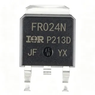
IRLR8726TRPBF - 30V 86A N-Channel StrongIRFET™ | Infineon
MPN: IRLR8726TRPBF ✓ Active| Qty | Unit Price | Extended |
|---|---|---|
| 1 | $0.89 | $0.89 |
| 10 | $0.74 | $7.40 |
| 100 | $0.58 | $58.00 |
| 500 | $0.46 | $230.00 |
| 1,000 | $0.38 | $380.00 |
| 3,000 | $0.32 | $960.00 |
IRLR8726TRPBF Overview
An N-channel power MOSFET is a voltage-controlled semiconductor switch that conducts current between drain and source when a positive gate-to-source voltage is applied, modulating a channel of electrons beneath the gate oxide. Power MOSFETs are the active switches used inside synchronous buck converters, half-bridge stages, eFuse blocks, hot-swap controllers, and motor-driver bridges, where they sit in the broader power-conversion hierarchy between the controller IC and the load. The DPAK (TO-252AA) is a single-die SMD package family descended from the through-hole TO-220, with a metal tab that doubles as the drain terminal and a heatsink mounting surface, enabling compact PCB designs that still dissipate tens of watts.
Key features include a typical gate charge of 15 nC, low R_DS(on) of 5.8 mΩ, a 75 W power dissipation rating at Tc, and the standard StrongIRFET™ robust body-diode ruggedness for unclamped inductive switching. These parameters make the part especially well-suited to synchronous rectification, where switching loss and conduction loss both directly determine overall converter efficiency.
The device uses Infineon's proven planar HEXFET process, providing a mature trade-off between RDS(on), gate charge, and avalanche ruggedness. The low 5.8 mΩ RDS(on) at 10 V VGS, combined with only 15 nC of gate charge, balances conduction and switching losses, enabling high-frequency operation without efficiency collapse.
Typical applications include high-frequency synchronous buck converters for processor power, high-side switching in 12 V/24 V industrial systems, battery protection circuits in lithium-ion packs, USB-PD power-path management, and DC motor control in eMobility and robotic systems.
When designing with this MOSFET, gate-drive strength must be sized to the 15 nC Qg - an under-driven gate causes slow turn-on and excessive switching loss. The exposed metal tab of the DPAK package must be soldered to the PCB copper pour to keep junction temperature within safe limits.
This page synthesizes distributor pricing, drop-in alternatives, and practical design notes not found in the manufacturer datasheet, providing engineering context for BOM selection and supply-chain decisions.
Drop-in alternatives for IRLR8726TRPBF — same package, pin-to-pin compatible. Different-package parts requiring PCB rework are excluded.
Variants in this series
Same-series models that are drop-in compatible with IRLR8726TRPBF (same form factor and footprint) — differing in MSL Level, Operating Junction Temperature, Package.
Quick Comparison Tool — Select alternative parts for side-by-side comparison:
IRLR8726TRLPBF
✅ Drop-In✓ In Stock
$0.36 / Unit
View Datasheet →IRLR8726PBF
✅ Drop-In📋 Reference alternative (not in catalog)
IRLR8743
✅ Drop-In📋 Reference alternative (not in catalog)
IRLR7843
✅ Drop-In📋 Reference alternative (not in catalog)
IRLR7833
✅ Drop-In📋 Reference alternative (not in catalog)
IRFR4104
✅ Drop-In📋 Reference alternative (not in catalog)
BSC011N03LSIATMA1
✅ Drop-In✓ In Stock
$1.32 / Unit
View Datasheet →IRLR8726TRPBF Maximum Ratings & Electrical Characteristics
| Manufacturer | Infineon Technologies |
| Part Number | IRLR8726TRPBF |
| Technology | StrongIRFET™ (HEXFET) |
| Channel Type | N-Channel |
| Drain-Source Voltage (V_DS) | 30 V |
| Continuous Drain Current (I_D) at T_C | 86 A |
| On-Resistance R_DS(on) max | 5.8 mΩ at V_GS = 10 V |
| Gate Charge Q_g (typ.) | 15 nC |
| Power Dissipation P_D | 75 W at T_C |
| Operating Junction Temperature | -55C to +175C |
| Package | TO-252AA (DPAK) |
| Mounting Type | Surface Mount |
| Number of Pins | 3 (Gate, Drain, Source) |
| RoHS Status | Compliant |
| Halogen-Free | Yes |
| MSL Level | 1 |
IRLR8726TRPBF Pin Configuration
| Pin 1 | Gate — Gate drive input - apply VGS=10V for full enhancement; threshold ~1-3V |
| Pin 2 | Drain (Tab) — Drain terminal - connected to the metal tab for thermal dissipation; solder to PCB copper pour |
| Pin 3 | Source — Source terminal - reference for gate drive; Kelvin connection recommended for high di/dt |
Safe Operating Area - IRLR8726TRPBF
Typical Applications
IRLR8726TRPBF is suitable for 6 applications: High-Frequency Synchronous Buck Converter, 24 V Industrial High-Side Switching, Lithium-Ion Battery Protection (BMS), USB-PD Power-Path Management, DC Motor Drive (H-Bridge Low-Side), Hot-Swap / eFuse Circuit.
High-Frequency Synchronous Buck Converter
The IRLR8726TRPBF is optimized for the synchronous-rectifier (low-side) position in 12 V input buck converters powering CPUs, GPUs, and ASICs. Its 5.8 mΩ R_DS(on) at 10 V VGS minimizes conduction loss, while 15 nC Qg keeps switching loss low at 300-500 kHz Fsw. The StrongIRFET™ body diode is rugged enough to handle dead-time conduction without requiring an external Schottky clamp. Used in VRM stages for datacom and telecom, paired with a high-side controller MOSFET, this part achieves >95% peak efficiency at 25 A load. Its 75 W power dissipation rating at T_C and DPAK package allow direct heatsink attachment for sustained high-current operation.
Recommended
24 V Industrial High-Side Switching
In 24 V industrial automation systems, the IRLR8726TRPBF serves as a low-R_DS(on) high-side switch for solenoid valves, actuators, and load disconnect circuits. The 30 V V_DS rating provides a 25% margin above 24 V nominal, accommodating inductive transients and load-dump events common in factory environments. With 86 A pulse capability and 5.8 mΩ R_DS(on), this part minimizes dissipation in continuous-current paths like motor windings and relay coils. The DPAK package with exposed metal tab enables direct PCB heatsink mounting for sustained operation. Industrial PLCs, motor starters, and process-control subsystems benefit from the StrongIRFET™'s avalanche-rated body diode that survives unclamped inductive kickback without external snubbers in most applications.
Recommended
Lithium-Ion Battery Protection (BMS)
The IRLR8726TRPBF functions as the discharge-control FET inside lithium-ion battery packs for eMobility, power tools, and portable energy storage. Its 5.8 mΩ R_DS(on) minimizes the voltage drop during high-current discharge, preserving usable battery capacity and reducing cell stress. The 30 V V_DS rating supports 7S-10S battery packs with adequate safety margin against transient overvoltages. With 86 A continuous current capability, a single IRLR8726TRPBF can support power-tool discharge currents up to 50 A continuous with proper PCB copper thermal management. The StrongIRFET™ ruggedness protects against reverse-polarity connection events common in user-replaceable battery systems, and the DPAK package allows compact pack-level PCB layouts.
Recommended
USB-PD Power-Path Management
In USB-PD 3.1 EPR applications delivering 28 V/36 V/48 V at 5 A or more, the IRLR8726TRPBF can serve as the VBUS load-switch or power-path ORing FET. The 30 V V_DS rating accommodates 20 V standard PDO with margin, and the 5.8 mΩ R_DS(on) limits voltage drop to 25 mV at 5 A - well within USB-PD tolerance. The 15 nC Qg enables fast turn-on/off under microcontroller PWM control for source-capability negotiation. Type-C docking stations, laptop chargers, and high-power hubs benefit from this part's low conduction loss and DPAK compactness. The exposed thermal tab provides direct heat-sinking into the Type-C connector's copper pour, keeping junction temperature in check during sustained high-power delivery.
Recommended
DC Motor Drive (H-Bridge Low-Side)
In brushed-DC motor H-bridge circuits for robotics, e-bikes, and small appliances, the IRLR8726TRPBF serves as the low-side switch in each half-bridge leg. Its 86 A continuous current capability supports motors drawing 20-40 A continuous with peaks to 80 A during stall or startup. The 5.8 mΩ R_DS(on) keeps I²R losses manageable during PWM duty cycles up to 100 kHz, while the StrongIRFET™ body diode handles inductive recirculation currents during dead time. The DPAK package's metal tab mounts directly to a copper heatsink for sustained motor-drive operation. For bidirectional control, pair with a P-channel high-side FET or use a complementary N-channel half-bridge topology with a dedicated gate driver.
Recommended
Hot-Swap / eFuse Circuit
The IRLR8726TRPBF is used as the main pass-FET in 12 V or 24 V hot-swap controllers and electronic fuse (eFuse) designs. Its 5.8 mΩ R_DS(on) minimizes voltage drop in the live insertion path, while its 86 A continuous rating supports high-power server and telecom plug-in cards. The StrongIRFET™'s linear-mode safe-operating-area (SOA) allows controlled inrush current limiting during hot-plug events without triggering thermal shutdown. Combined with a hot-swap controller IC, the IRLR8726TRPBF provides programmable current limiting, fault isolation, and ORing capability in redundant 12 V distribution. The DPAK package with copper-pour heatsink ensures the part survives the high SOA stress during inrush without damage.
Recommended
Recommended Products Summary
Engineering reference data for IRLR8726TRPBF — comparison, design guidance, and compliance information.
Selection Guide
Comparison with Alternatives
| Parameter | This Product | IRLR8726TRLPBF | IRLR8743 | IRLR7833 | IRFR4104 |
|---|---|---|---|---|---|
| Brand | Infineon | Infineon | Infineon | Infineon | Infineon |
| Package | TO-252AA (DPAK) | TO-252AA (DPAK) - same | TO-252AA (DPAK) - same | TO-252AA (DPAK) - same | TO-252AA (DPAK) - same |
| V_DS max | 30 V | 30 V | 30 V | 30 V | 40 V |
| Continuous Drain Current (Tc) | 86 A | 86 A | 80 A | 75 A | 77 A |
| R_DS(on) max @ VGS=10V | 5.8 mΩ | 5.8 mΩ | 3.2 mΩ (lower) | 9.4 mΩ (higher) | 5.6 mΩ |
| Typical Gate Charge Qg | 15 nC | 15 nC | 20 nC | 8.5 nC (lower) | 50 nC (higher) |
| Power Dissipation Pd | 75 W | 75 W | 75 W | 75 W | 75 W |
| Technology Family | StrongIRFET™ | StrongIRFET™ | StrongIRFET™ | StrongIRFET™ | HEXFET |
Key Differentiators
- Lowest R_DS(on) in the StrongIRFET™ 30 V DPAK family at this current class (vs IRLR7833)
- Higher V_DS rating for 24 V industrial bus applications (vs IRFR4104)
- Tape-and-reel packaging optimized for automated SMT assembly (vs IRLR8726PBF)
Design Notes
Estimated: at 30 A continuous through 5.8 mΩ R_DS(on), conduction loss is P = I² × R = 900 × 0.0058 ≈ 5.2 W. The DPAK package has θJA ≈ 50 C/W on a 1 sq inch 2 oz copper pour at 25C ambient, giving a 260C junction temperature rise - exceeding the 175C limit. For 30 A continuous, expand copper area to ≥2 sq inches or add an active heatsink. Use junction-to-case thermal resistance θJC ≈ 1.67 C/W to compute case temperature rise: at 75 W dissipation, ΔT = 75 × 1.67 ≈ 125C above case temperature, requiring an aggressive cooling solution.
Place the gate-drive resistor (typically 10-100 Ω) as close to the gate pin as possible to dampen parasitic ringing from the gate-source capacitance and source-lead inductance. Use a Kelvin source connection - route the gate-drive return directly to the S pin, NOT to the power-source PCB trace, to eliminate common-source inductance that slows switching and causes ground bounce. The DPAK drain tab should be soldered to a copper pour at least 50 × 50 mm to provide the necessary thermal dissipation path; vias under the tab to internal ground planes further reduce thermal resistance.
Do not operate the IRLR8726TRPBF above its 30 V V_DS maximum - even brief overshoot from unclamped inductive switching will permanently damage the device. Add a TVS diode or RC snubber across the drain-source path if inductive kickback exceeds 24 V. The body diode has a reverse-recovery charge that can cause shoot-through in synchronous buck topologies - ensure controller dead-time is set to at least 50 ns to prevent cross-conduction. Finally, gate-source ESD damage is common during handling - observe JEDEC J-STD-033 ESD precautions and use anti-static packaging until board assembly.
Compliance Information
PBF suffix in part number indicates lead-free (Pb-free) plating per Infineon product page. RoHS and REACH compliant per EU Directive 2015/863. Not AEC-Q100 qualified - use IRFR8714TRPBF or similar Q-graded part for automotive applications.